Chair spring tension control

a tension control and chair technology, applied in the direction of seating furniture, vehicle seats, transportation and packaging, etc., can solve the problem of some awkward us

Inactive Publication Date: 2005-05-19
RAM MACHINE 1990
View PDF6 Cites 5 Cited by
  • Summary
  • Abstract
  • Description
  • Claims
  • Application Information

AI Technical Summary

Benefits of technology

[0009] Preferably, fixed wedge components are provided both on the lower housing part and on the inner end of the spring and the moveable wedge component acts between oppositely outwardly inclined surfaces of the fixed wedge components. In fact, the wedge means preferably is symmetrical and includes two moveable wedge components that move i

Problems solved by technology

While this form of spring tension control works

Method used


Image

  • Chair spring tension control
  • Chair spring tension control
  • Chair spring tension control

Examples


Embodiment Construction

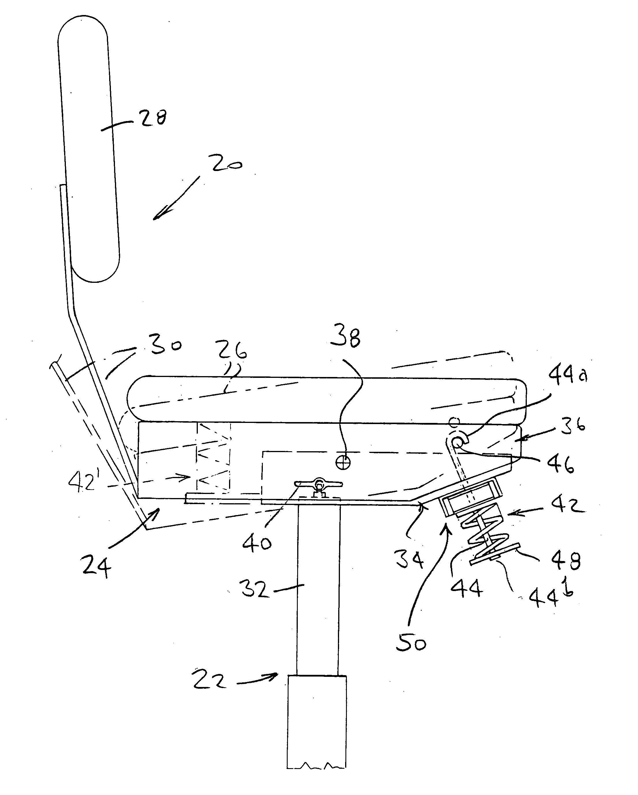
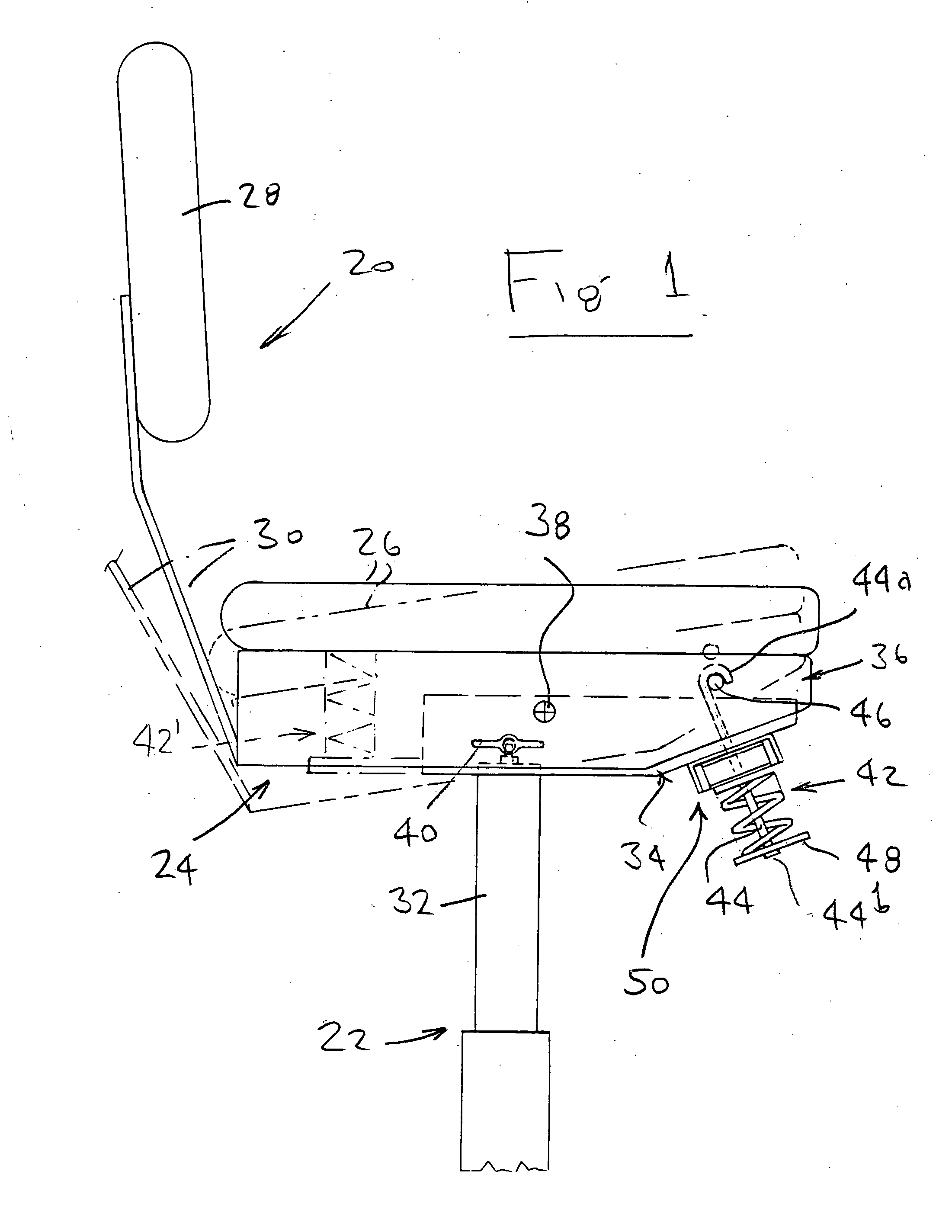
[0016] Referring first to FIG. 1, a typical office chair is seen to comprise a seat / back assembly 20 which is coupled to a chair base 22 by a mechanism 24 which allows controlled tilting of the seat / back assembly with respect to the base. The mechanism is shown in full lines in a normal rest position in which the seat (26) is generally horizontal, and in ghost outline in a tilted back position in which the seat 26 is rearwardly inclined, also as shown in ghost outline. The back 28 is connected to the tilt mechanism by an arm 30 (also seen in FIG. 2) so that the back also tilts. In this embodiment, the orientation of the seat 26 and back 28 with respect to one another is fixed, although the tilt mechanism can be designed to allow tilting movement of the back with respect to the seat, as is well known in the art.

[0017] The chair base is essentially conventional and in this case includes a telescopic upright column 32 that carries the tilt mechanism 24. Mechanism 24 has a fixed lower ...


PUM


Abstract

A tilt mechanism for an office chair includes a spring tension control that incorporates a wedge arrangement including a moveable wedge component that is displaceable laterally by turning a control knob below the seat of the chair, to force fixed wedge components apart and increase the spring tension. Turning the knob in the opposite direction reduces spring tension.

Description

FIELD OF THE INVENTION [0001] This invention relates generally to tilt mechanisms for office chairs, and is concerned more particularly with a spring tension control for such a mechanism. BACKGROUND OF THE INVENTION [0002] A typical office chair includes a seat / back assembly which is coupled to a chair base by a mechanism that allows controlled tilting of the seat / back assembly with respect to the base. The base usually has an upright post which carries a lower, stationary housing part of the tilt mechanism. Pivoted to the stationary housing part is an upper housing part that carries the seat / back assembly. The back may or may not be movable with respect to the seat. A spring extends between the two housing parts of the tilt mechanism and normally maintains the parts in a rest position with respect to one another. When a person sitting on the chair leans back, the upper housing part tilts with respect to the lower housing part and the spring is compressed, cushioning the tilting mov...

Claims


Application Information

Patent Timeline
IPC IPC(8): A47C1/02A47C1/024A47C1/027A47C1/032
CPCA47C1/03255A47C1/03272A47C1/03266
Inventor DOBKIN, ISRAELCYBULSKY, MARIAN
Owner RAM MACHINE 1990
Why Eureka
Try Eureka