Ethernet network synchronization systems and methods

a network synchronization and network technology, applied in the field ofethernet networks, can solve the problems of adding timing jitter and delay, not being available to further nodes, and most conventional networks do not have ptp-capable nodes, so as to reduce the number of slaves and achieve high stability

Active Publication Date: 2011-08-18
CIENA
View PDF12 Cites 115 Cited by
  • Summary
  • Abstract
  • Description
  • Claims
  • Application Information

AI Technical Summary

Benefits of technology

In an exemplary embodiment, an Ethernet network includes one or more non-clocked nodes without synchronous Ethernet (Sync-E) or IEEE 1588 capability; an end node with a clock providing an Ethernet connection including a reference clock through at least one of the one or more non-clocked nodes; and a clock regeneration node disposed after the at least of one of the one or more non-clocked nodes receiving the Ethernet connection and regenerating the reference clock. The clock regeneration node may be located at a drop off point of the Ethernet connection. The clock regeneration node is configured to operate according to both synchronous Ethernet (Sync-E) and IEEE 1588 protocols. The Ethernet network further includes one or more Sync-E nodes receiving the Ethernet connection after the clock regeneration node, wherein the end node operates according to the IEEE 1588 protocols, and wherein the one or more Sync-E nodes operate according to the Sync-E protocols thereby reducing a number of slaves for IEEE 15888. The clock regeneration node may be configured to regenerate Sync-E for downstream nodes without requiring Sync-E upstream, and wherein the reference clock is according to the IEEE 1588 protocols and operable to transverse asynchronous nodes while being rebuilt at the clock regeneration node. Optionally, the Ethernet connection traverses no more than five consecutive non-clocked nodes prior to the clock regeneration node. Alternatively, the Ethernet connection traverses no more than one consecutive non-clocked node prior to the clock regeneration node. Also, the Ethernet connection may traverse more than one consecutive non-clocked node prior to the clock regeneration node, and the Ethernet network further includes a high stability local oscillator (oven controlled crystal or atomic) at the clock regeneration node. At each of the one or more non-clocked nodes is configured to provide packets from the Ethernet connection with the clock reference in a high priority queue. The end node may include physical interfaces and circuitry configured to timestamp ingress and egress packets relative to a local clock; a processor operating according to the IEEE 1588 protocols, the processor receiving timestamps and providing one or more reference clocks to an input selector; and a phase lock loop receiving an output of the input selector and providing an output reference clock to the processor. The Ethernet network further includes a best multi source clock selection algorithm and a clock selection holdover algorithm for the end node. The one or more Sync-E nodes each include physical interfaces providing a reference clock to a clock input selector; circuitry receiving synchronization status messages from the physical interfaces and providing the synchronization status messages to the clock input selector; and a phase lock loop receiving an input from the clock input selector and providing an output to the physical interfaces. The Ethernet network further includes a best multi source clock selection algorithm and a clock selection holdover algorithm for the end clock node.
In another exemplary embodiment, an Ethernet node includes physical interfaces and circuitry configured to timestamp ingress and egress packets relative to a local clock; a processor operating according to the IEEE 1588 protocols, the processor receiving timestamps and providing one or more reference clocks to an input selector; and a phase lock loop receiving an output of the input selector and providing an output reference clock to the processor; wherein the Ethernet node is configured as one of a Boundary Clock node, a Transparent Clock node, or an Ordinary Clock node. The Boundary Clock node is configured to receive a reference clock in an Ethernet connection previously traversing asynchronous nodes and to regenerate the reference clock. The Ethernet node is configured as a Boundary Clock node receiving the Ethernet connection from one or more previous asynchronous nodes. The Ethernet node further includes an external reference clock input to the input selector; a best multi source clock selection algorithm and; a clock selection holdover algorithm.
In another exemplary embodiment, a method includes transmitting an Ethernet connection with a reference clock in a network; adapting quality of service in at least one Transparent Clock node in the network for the Ethernet connection; and regenerating the reference clock after the Ethernet connection transverses at least one non-clocked node in the network. The method further includes receiving a plurality of reference sources at a node in the network, the reference sources including one or more of IEEE 1588 sources, Synchronous Ethernet (Sync-E) sources, SONET / SDH sources, Network Time Protocol sources, and external reference sources; determining quality metrics of the plurality of reference sources; selecting one of the plurality of reference sources based on the quality metrics; performing an adaptive / predictive filter algorithm; and inputting the selected source to a phase lock loop. The method further includes selecting one of the plurality of reference sources based on a tunnel technology including at least PBB-TE or MPLS-TP.

Problems solved by technology

For example if a single node is not Sync-E compliant then Sync-E will not traverse that node and thus will not be available to further nodes.
This is problematic as most currently deployed Ethernet devices (e.g., switches) do not support Sync-E nor do most new devices.
However, switches in a network (between the source and slave) add timing jitter and delay due to traffic loading variations.
Thus, all nodes must include such support for PTP, but most conventional networks do not have PTP-capable nodes requiring a newly built network to support PTP.
Operating PTP at some nodes and not others will result in clocking issues such as inability to reach the required stratum or other clocking requirements at the end node, long convergence times, and additional costs of the end node equipment (high stability local oscillator).

Method used


Image

  • Ethernet network synchronization systems and methods
  • Ethernet network synchronization systems and methods
  • Ethernet network synchronization systems and methods

Examples


Embodiment Construction

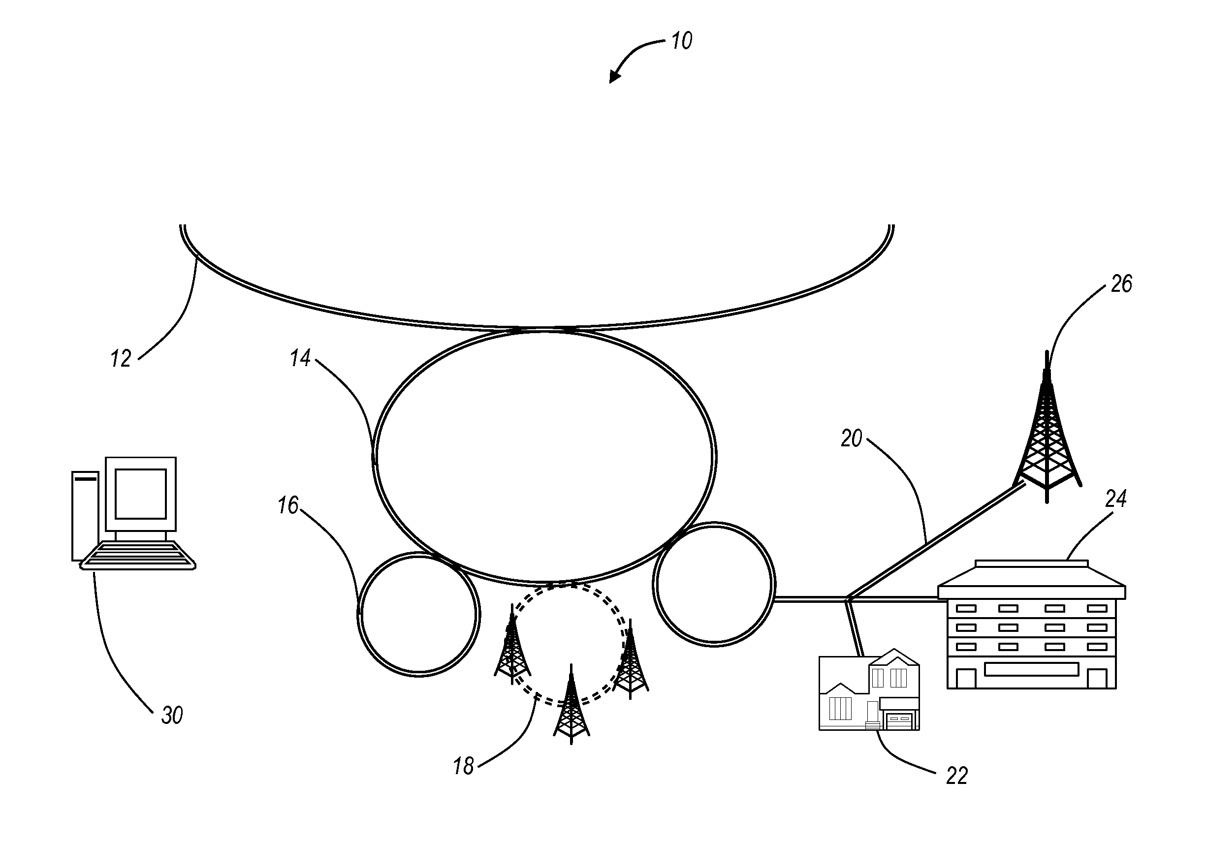
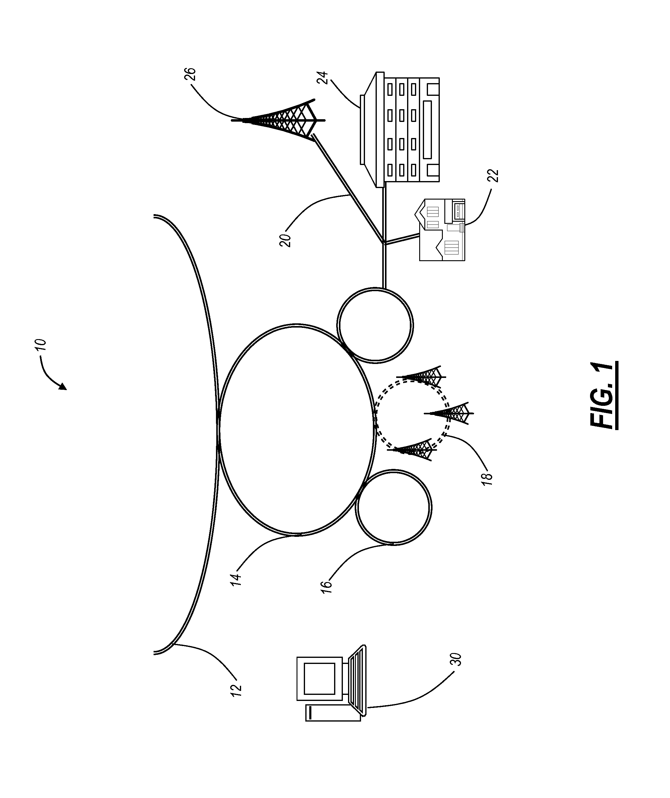
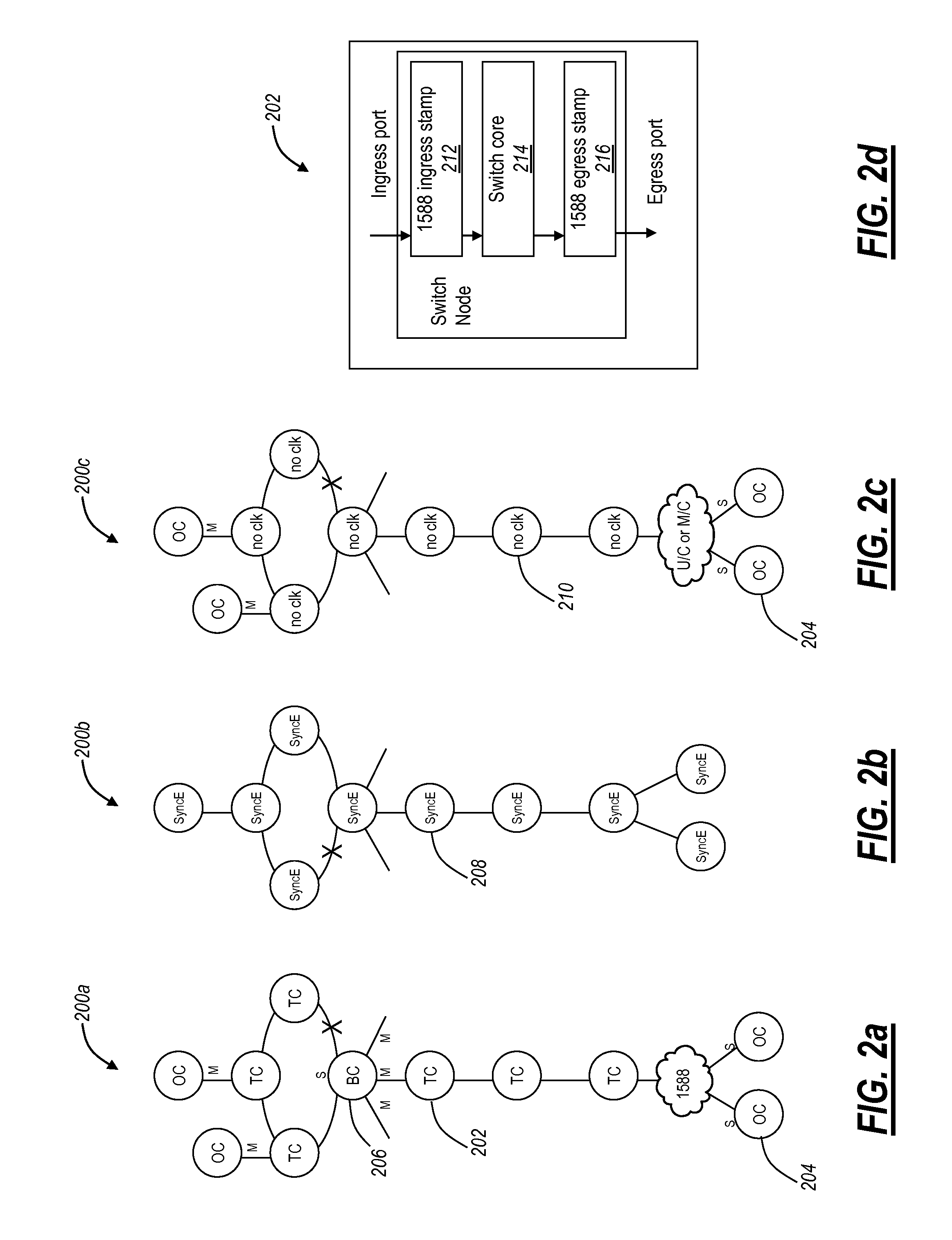
In various exemplary embodiments, the present invention relates to Ethernet synchronization systems and methods that combine Sync-E and PTP 1588 algorithms. The present invention includes systems and methods for Ethernet networks and node configurations that include a set of rules on node placement, such as Boundary Clock (BC) nodes and Sync-E nodes, a clock selection algorithm, a holdover algorithm, and the like. Advantageously, the present invention provides an architecture that allows practical and real-world useful clock propagation through placement of BCs and Sync-E nodes for best performance. Each of the Sync-E and PTP 1588 Standards define a theoretical general set of tools and guidelines with gaps in functionality and application specific details. Practical experience and theoretical design are embodied in the present invention to define a very specific set of rules on how to build a practical, reliable, and accurate packet based synchronization network. The present inventi...


PUM


Abstract

The present disclosure relates to Ethernet synchronization systems and methods that combines Synchronous Ethernet (Sync-E) and Precision Time Protocol (PTP) IEEE 1588 algorithms. The present invention includes systems and methods for Ethernet networks and node configurations that include a set of rules on node placement, such as Boundary Clock (BC) nodes and Sync-E nodes, a clock selection algorithm, a holdover algorithm, and the like. Advantageously, the present invention provides an architecture that allows practical and real-world useful clock propagation through placement of BCs and Sync-E nodes for best performance. Practical experience and theoretical design are embodied in the present invention to define a very specific set of rules on how to build a network capable of providing accurate and reliable synchronization. The present invention includes clock selection that unifies Sync-E and 1588 algorithms.

Description

FIELD OF THE INVENTIONThe present invention relates generally to Ethernet networks. More particularly, the present invention relates to Ethernet network synchronization systems and methods utilizing Synchronous Ethernet (referred to herein as “Sync-E”) and various IEEE 1588 Precision Time Protocol (PTP) standards in a combined fashion along with a set of rules on node placement, such as Boundary Clock (BC) nodes and Sync-E nodes, a clock selection algorithm, a holdover algorithm, and the like.BACKGROUND OF THE INVENTIONConventionally, networks are deployed in tiered architectures utilizing a variety of transport media, e.g. optical fiber, wireless, coaxial cable, twisted pair, etc., and layers. Further, access, aggregation, long-haul, and other network types may use a variety of protocols, such as SONET, SDH, Optical Transport Network (OTN), and the like, as the underlying physical protocol. OTN is generally defined in various ITU-T recommendations, such as ITU-T Recommendation G.70...

Claims


Application Information

Patent Timeline
Patent Type & Authority Applications(United States)
IPC IPC(8): H04L12/56H04J3/06
CPCH04J3/0641H04J3/0644H04L12/413H04J3/0667H04J3/0673H04J3/0658
Inventor RIVAUD, DANIELGAZIER, MICHAELDZIAWA, MICHAEL
Owner CIENA
Why Eureka
Try Eureka