Pattern matching device and pattern matching method

a technology of pattern matching and matching device, which is applied in the field of pattern matching device and matching method, can solve the problems of increasing the volume of data to be transferred, causing a bottleneck in the process, and achieve the effect of reducing the amount of image data transmitted

Inactive Publication Date: 2011-08-18
NEC CORP
View PDF4 Cites 61 Cited by
  • Summary
  • Abstract
  • Description
  • Claims
  • Application Information

AI Technical Summary

Benefits of technology

[0024]According to the present invention, an image containing plural types of biometric patterns is obtained; plural types of biometric pattern are separated and extracted from the image; and matching is performed on the basis of the separated and extracted plural types of biometric patterns. Therefore, it is possible to reduce an image data transmitted from a unit in an image capturing system to a unit in a process system to a relative low volume.
[0025]According to the present invention, it is possible to provide a pattern matching device and a pattern matching method capable of obtaining an image containing plural types of biometric patterns, separating and extracting plural types of biometric patterns from the image, thereby to implement matching.

Problems solved by technology

Accordingly, there is a possibility that the resulting increase in the volume of data to be transferred leads to a bottle neck of the process.
This causes a serious problem especially in the case of increasing the available speed at which the finger can be scanned or in the case of increasing the resolution of the image data.

Method used


Image

  • Pattern matching device and pattern matching method
  • Pattern matching device and pattern matching method
  • Pattern matching device and pattern matching method

Examples


first exemplary embodiment

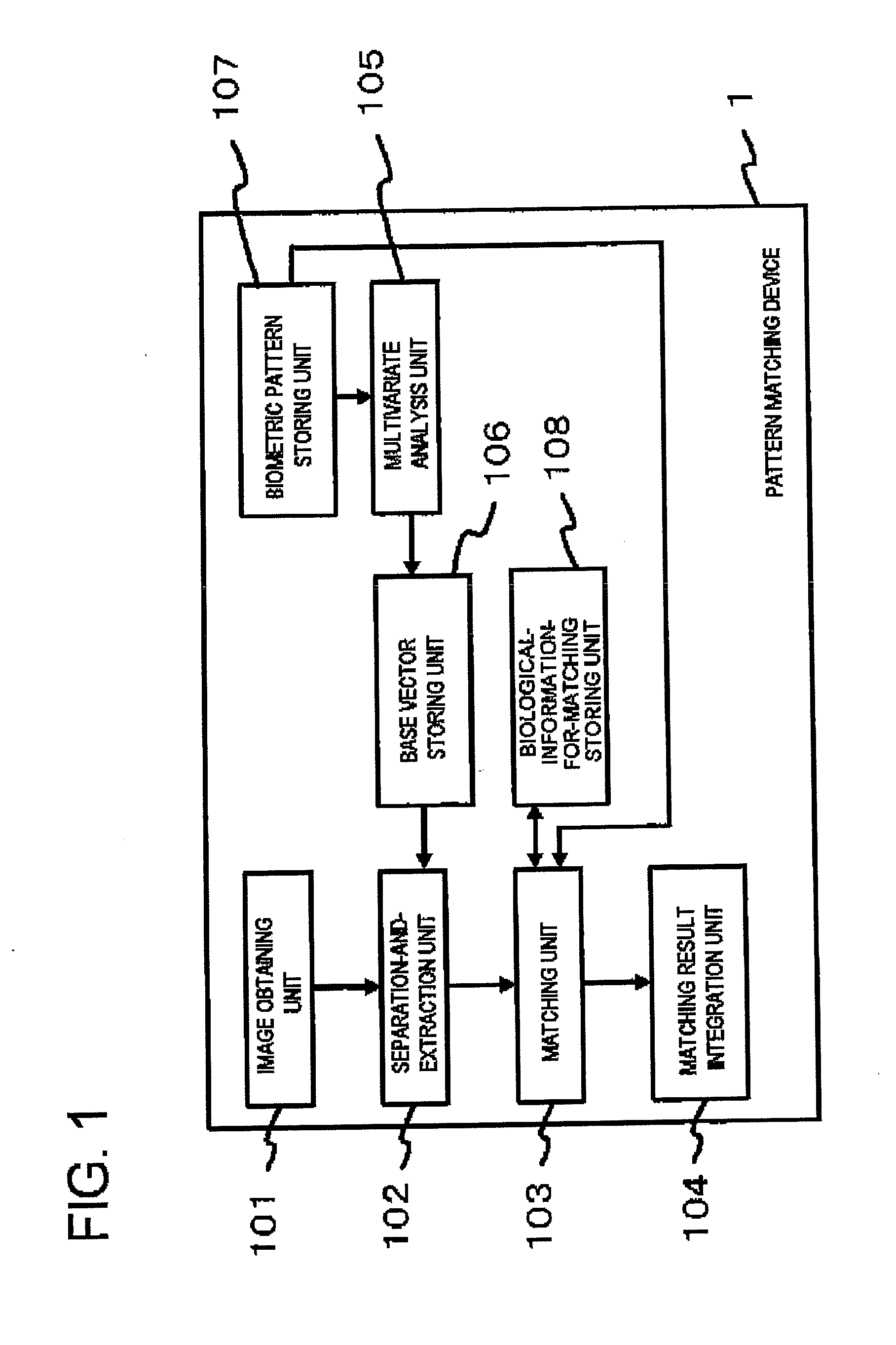
[0035]FIG. 1 is a block diagram of a pattern matching device 1 according to the exemplary embodiment of the present invention. The pattern matching device 1 may include an image obtaining unit 101 that obtains an image of a subject containing plural types of biometric patterns; a separation and extraction unit 102 that separates and extracts the respective types of biometric patterns from the image; and, a matching unit 103 that matches each of the separated and extracted plural types of biometric patterns against pre-registered biological information for matching so as to obtain plural matching results. The term “biological information for matching” refers to a biometric pattern (or information representing its feature) registered in advance to be compared and matched with a biometric pattern (or information representing its feature) extracted from an image obtained by the pattern matching device 1.

[0036]The pattern matching device 1 may further include a matching result integratio...

second exemplary embodiment

[0099]A second exemplary embodiment according to the present invention will be described. In this exemplary embodiment, an image obtained by the image obtaining unit 101 is a multispectral image formed by at least four color components, and, pixels of a biometric pattern extracted by the separation-and-extraction unit 102 may be expressed by the inner product of the biometric base vector and the image vector in at least four or more dimension. However, the number of color components contained in the image obtained by the image obtaining unit 101 is equal to the number of color components of the image stored in the biometric pattern storing unit 107, and the dimension of the biometric base vector is equal to that of the image vector.

[0100]FIG. 5 illustrates an example of the image obtaining unit 101 capable of obtaining the multispectral image. The image obtaining unit 101 may include: plural half-mirrors 502 that separates an optical path of a light emitted through an imaging lens 5...

third exemplary embodiment

[0108]A third exemplary embodiment of the present invention is modified so as to be able to obtain a multispectral image by a configuration different from that in the second exemplary embodiment. A configuration of the image obtaining unit 101 according to this exemplary embodiment is illustrated in FIG. 6. The image obtaining unit 101 may include: a half-mirror 602 that separates an optical path of a light through a imaging lens 607 into at least two paths; an infrared ray cutting filter 603 that blocks an infrared ray contained in a light of one optical path of the at least two optical paths separated by the half-mirror 602 to pass through; a bandpass filter 604 that allows almost a half wavelength band of each of red, green and blue wavelength bands contained in the light of the other optical path of the at least two optical paths separated by the half-mirror 602; a dichroic prisms 605 that each separate the light passing through the infrared ray cutting filter 603 and the light ...


PUM


Abstract

A pattern matching device 1 includes an image obtaining unit 101 that obtains an image of a subject containing plural types of biometric patterns. Further, the pattern matching device 1 includes a separation-and-extraction unit 102 that separates and extracts the plural types of biometric patterns from the image. Yet further, the pattern matching device 1 includes a matching unit 103 that matches the separated and extracted plural types of biometric patterns against pre-registered biological information for matching, thereby to derive plural matching results.

Description

TECHNICAL FIELD[0001]The present invention relates to a pattern matching device and a pattern matching method. In particular, the present invention relates to a pattern matching device and a pattern matching method for verifying an individual using a fingerprint pattern and a pattern of a blood vessel such as a vein.BACKGROUND ART[0002]In recent years, automated-teller machines, electronic commerce systems, door lock systems and the like have employed a matching operation based on biological information specific to each individual (fingerprint pattern, blood vessel pattern such as vein, iris of eye, voice print, face, palm shape, etc.) as a means for identifying users. Further, there is proposed a technique for enhancing reliability of matching results by combining plural types of the biological information described above at the time of the matching operation.[0003]As a technique of this type, Patent Document 1 (Japanese Patent Application Laid-open No. 2008-20942) describes an ind...

Claims


Application Information

Patent Timeline
Patent Type & Authority Applications(United States)
IPC IPC(8): G06K9/00
CPCA61B5/117A61B5/1172G06K2009/00932G06K9/00892G06K2009/0006A61B5/489G06V40/1341G06V40/70G06V40/14A61B5/1171
Inventor NAKAMURA, YOICHIKAMEI, TOSHIO
Owner NEC CORP
Why Eureka
Try Eureka