Electrical signal connector

a technology of electrical signal and connector, which is applied in the direction of connections, line/current collector details, electrical apparatus, etc., can solve the problems of poor contact, signal transmission instability, and high stability of signal transmission, and achieve excellent waterproof effect, prevent water leakage, and facilitate quick and accurate installation of coaxial cables.

Inactive Publication Date: 2011-08-18
LU YUEH CHIUNG
View PDF26 Cites 1 Cited by
  • Summary
  • Abstract
  • Description
  • Claims
  • Application Information

AI Technical Summary

Benefits of technology

[0013]The present invention has been accomplished under the circumstances in view. It is the main object of the present invention to provide an electrical signal connector, which facilitates quick and accurate installation of a coaxial cable, without causing deformation of the coaxial cable or any damage to the aluminum foil shield of the coaxial cable. It is another object of the present invention to provide an electrical signal connector, which achieves excellent waterproof effects.
[0014]To achieve these and other objects of the present invention, an electrical signal connector comprises a locknut, a cylindrical casing fastened to one end of the locknut, a core tube inserted into the locknut and the cylindrical casing and a barrel mounted on the cylindrical casing. The locknut is made of metal. The cylindrical casing is made of an elastic material. The locknut comprises a retaining portion located on one end thereof. The cylindrical casing comprises a mounting base for fastening to the retaining portion of the locknut. The inner diameter of the retaining portion of the locknut is slightly smaller than the outer diameter of the mounting base of the cylindrical casing so that fastening the mounting base of the cylindrical casing to the retaining portion of the locknut causes a retaining portion of the mounting base of the cylindrical casing to be forced into engagement with a stepped shoulder of retaining portion of the locknut, and the stepped shoulder will be compressed to seal the gap upon between the cylindrical casing and the locknut and to prevent water leakage upon installation of an external matching electrical connector. After mounting of the barrel on the cylindrical casing, a part of the cylindrical casing is compressed by the barrel to form a neck portion, facilitating quick and accurate installation of a coaxial cable.
[0015]Further, after insertion of the core tube into the locknut and the cylindrical casing, the core tube can be moved axially relative to the locknut and the cylindrical casing before installation of a coaxial cable, and a packing portion of the core tube is forced into engagement with a mounting hole in the cylindrical casing to secure the core tube to the locknut and the cylindrical casing firmly in position after installation of a coaxial cable in the electrical signal connector. Further, after installation of the barrel in the cylindrical casing, a hooked portion of the barrel engages the periphery of the tubular body of the cylindrical casing, and the tubular body of the cylindrical casing is compressed by a tapered inner surface portion and contracted inner wall portion of the barrel to deform, forming the desired neck portion. When inserting a coaxial cable into the core tube, the applied thrust force will force a packing portion of the core tube away from the peripheral wall of a mounting hole in the cylindrical casing, allowing axial movement of the core tube in the mounting hole of the cylindrical casing and insertion of the copper core (center conductor), aluminum foil shield and inner dielectric insulator of the coaxial cable into the core tube. Thereafter, the core tube is pushed back to force the packing portion into the mounting hole of the cylindrical casing, causing the braided metal wrapper (woven copper shield) surrounded and outer plastic sheath of the coaxial cable to be stopped in place by the neck portion of the cylindrical casing, and therefore the neck portion secures the coaxial cable in place, assuring connection stability and avoiding disconnection of the coaxial cable from the cylindrical casing.

Problems solved by technology

Following fast development of communication technology, signal transmission requires high stability and rapid speed.
However, if the crimping tube A2 is not kept in alignment with the seam line A11 during installation, the crimping tube A2 may break.
Further, when the cable B is stretched accidentally, the center conductor B1 of the cable B may be forced out of position, causing a poor contact and signal transmission instability.
This installation procedure is inconvenient.
According to this design, the locknut C1 of the electrical signal connector C has a big size and high manufacturing cost, and can only be rotated by hand without tool.
Fastening the locknut C1 by hand cannot achieve high connection tightness.
In actual use, this design of radial compression type coaxial cable end connector still has drawbacks.
After insertion of the cable B into the inner post D2, the center conductor B1 of the cable B may be deformed, and the aluminum foil shield B3 of the cable B may be damaged, causing signal transmission instability.
This design facilitates alignment of the cable during installation, however it still has drawbacks as follows:1. This design of coaxial cable connector consists of a number of component parts, complicating installation.
Further, the guide tube F3 must be thrown away after its service, not allowing for a repeated use.

Method used


Image

  • Electrical signal connector
  • Electrical signal connector
  • Electrical signal connector

Examples


Embodiment Construction

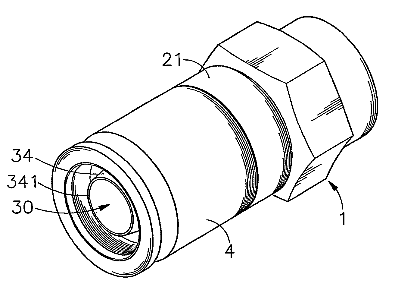
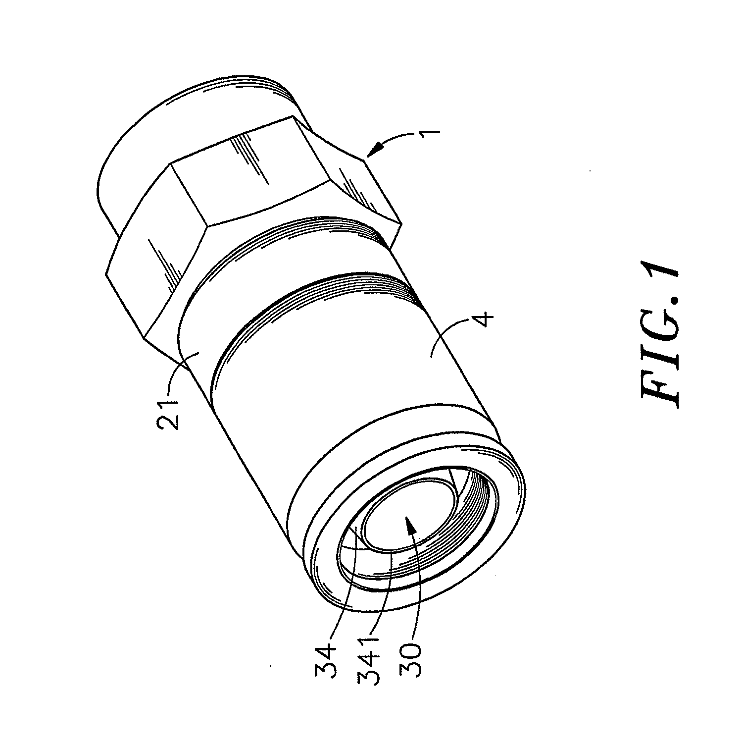
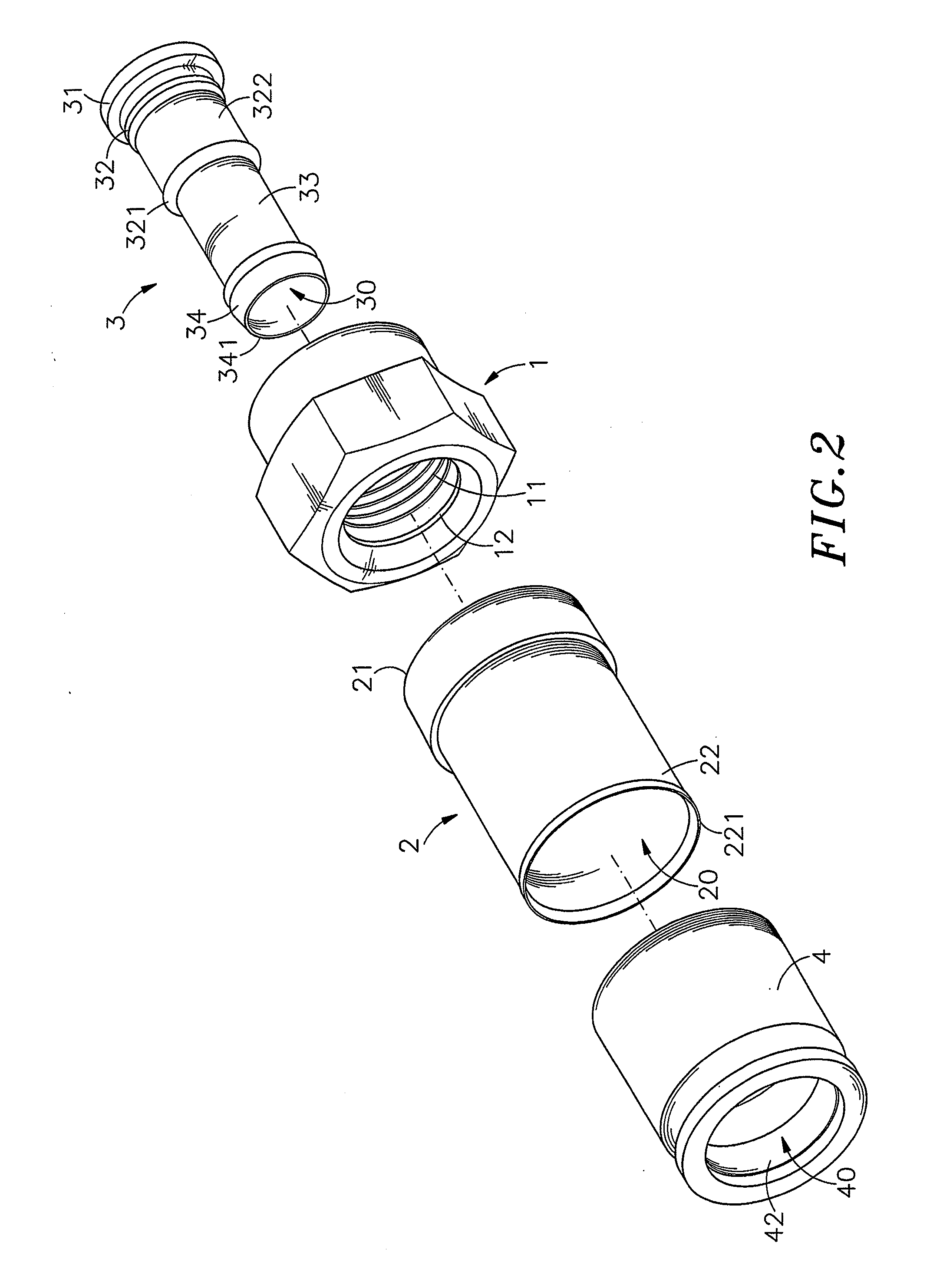
[0031]Referring to FIGS. 1-4, an electrical signal connector in accordance with the present invention is shown comprising a locknut 1, a cylindrical casing 2, a core tube 3 and a barrel 4.

[0032]The locknut 1 is a metal member shaped like a polygonal screw nut, having a center hole 10 axially extending through opposing front and rear sides thereof, an inner thread 11 extending around the inside wall within the center hole 10, an orifice 111 defined in the rear side in communication with one end of the center hole 10, and a retaining portion 12 located on the front side around the center hole 10. The retaining portion 12 comprises a stepped shoulder 121 extending around the other end of the center hole 10 and a beveled abutment face 122 located on the outer side of the stepped shoulder 121. Further, the locknut 1 can be made of copper, ferrite, or any of a variety of metal alloys.

[0033]The cylindrical casing 2 is made of an elastic material, such as plastics or rubber, having a tubula...


PUM


Abstract

An electrical connector includes a metal locknut having an inner thread, an orifice defined and a retaining portion, an elastic cylindrical casing having a mounting base for fastening to the retaining portion of the locknut, a core tube inserted into the locknut and the cylindrical casing for receiving the center conductor and inner dielectric insulator of a coaxial cable and having a barbed flange for engaging the braided metal wrapper of the coaxial cable, a first tubular wall and a packing portion connected for engaging into the mounting base of the cylindrical casing, and a barrel mounted on the cylindrical casing and having a contracted inner wall portion adapted for compressing the cylindrical casing.

Description

[0001]This application claims the priority benefit of Taiwan patent application number 099203163 filed on Feb. 12, 2010.BACKGROUND OF THE INVENTION[0002]1. Field of the Invention[0003]The present invention relates an improved structure of electrical signal connector and more particularly, to such an electrical signal connector, which facilitates alignment, insertion and installation of a mating cable. Subject to the characteristic that the barbed flange of the core tube is suspending in the cylindrical casing near the end edge of the tubular body, the invention facilitates mounting of a mating cable without causing damage to the aluminum foil shield of the mating cable.[0004]2. Description of the Related Art[0005]Following fast development of communication technology, signal transmission requires high stability and rapid speed. In consequence, different communication wire materials, from the early flat cable design to the modern round cable and optical cable designs, have been creat...

Claims


Application Information

Patent Timeline
Patent Type & Authority Applications(United States)
IPC IPC(8): H01R9/05
CPCH01R43/00H01R9/0524
Inventor LU, YUEH-CHIUNG
Owner LU YUEH CHIUNG
Why Eureka
Try Eureka