
Method for buffering streaming data and a terminal device

a terminal device and streaming data technology, applied in the field of buffering streaming data, can solve problems such as inability, and achieve the effect of improving the end-user experien

Active Publication Date: 2011-08-18
GOODIX TECH HK CO LTD
View PDF38 Cites 12 Cited by
  • Summary
  • Abstract
  • Description
  • Claims
  • Application Information

AI Technical Summary

Benefits of technology

[0012]It is an object of the invention to provide a method of buffering streaming data and a terminal device which enables the end-user experience by shortening significantly the buffering time.
[0019]According to a further aspect of the invention, the rendering data rate is increased with an increased filling of the terminal buffer.
[0023]The invention proposes to reduce buffering latency (for example to about 2 s) regardless of the network type, and to reduce the rendering data rate (playback speed), and then smoothly restoring normal rendering data rate (e.g. to the same rate as the server data rate). This change can be performed in such a way that there is no visible / hearable distortion, in other words such that an end-user noticeable artifact can be avoided. This is achieved by changing the video sample duration (e.g. display each frame during 50 ms rather than 40 ms) and using an audio time stretching algorithm to change sample duration without impacting the pitch.
[0027]The steps will be explained with reference to the accompanying drawings. An important advantage of the invention is that an operator can provide a better end-user experience without performing any infrastructure change, neither of the server nor of the network.

Problems solved by technology

This is not possible according to the prior art as there the rendering will be stopped if not sufficient data is present in the terminal buffer.

Method used


Image

  • Method for buffering streaming data and a terminal device
  • Method for buffering streaming data and a terminal device
  • Method for buffering streaming data and a terminal device

Examples


first embodiment

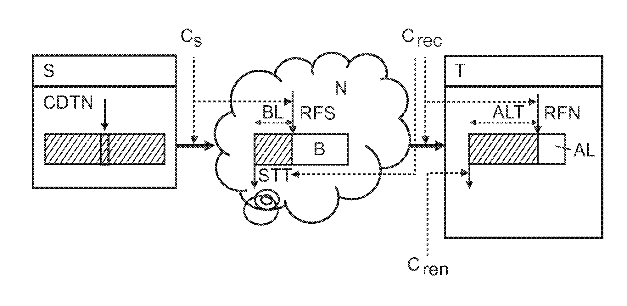
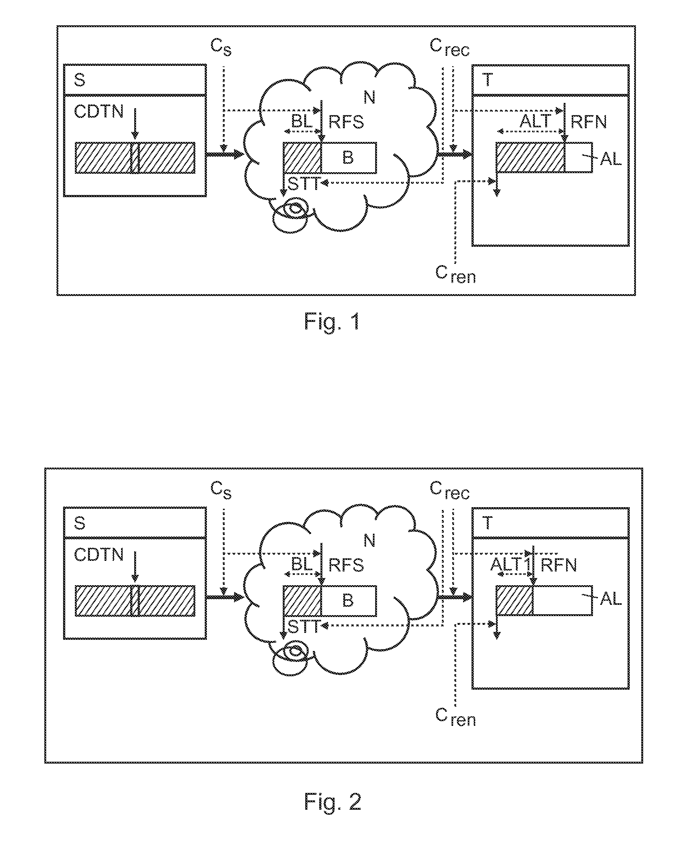
[0035]FIG. 2 shows a schematic representation of a data processing system according to a The data processing system comprises a server S, at least one terminal T and a network N. Streaming data can be transmitted from the server S at a server data rate CS via the network N and from the network N at a reception data rate Crec to the terminal T. The terminal comprises a buffer AL for buffering the streaming data. The terminal T can render the buffered data at a rending data rate Cren. The network N can comprise a buffer B with a network buffering time BL. The buffer B contains data received from the server RFS but not yet sent to the terminal STT. In FIG. 2, a method of buffering the streaming data is depicted, where normal buffering during a shorter time slot is implemented.

[0036]The first step comprises performing buffering within a time slot that comprises substantially ⅓ of the time slot for normal terminal buffering. The first step represents the initial stage; the player or ter...

second embodiment

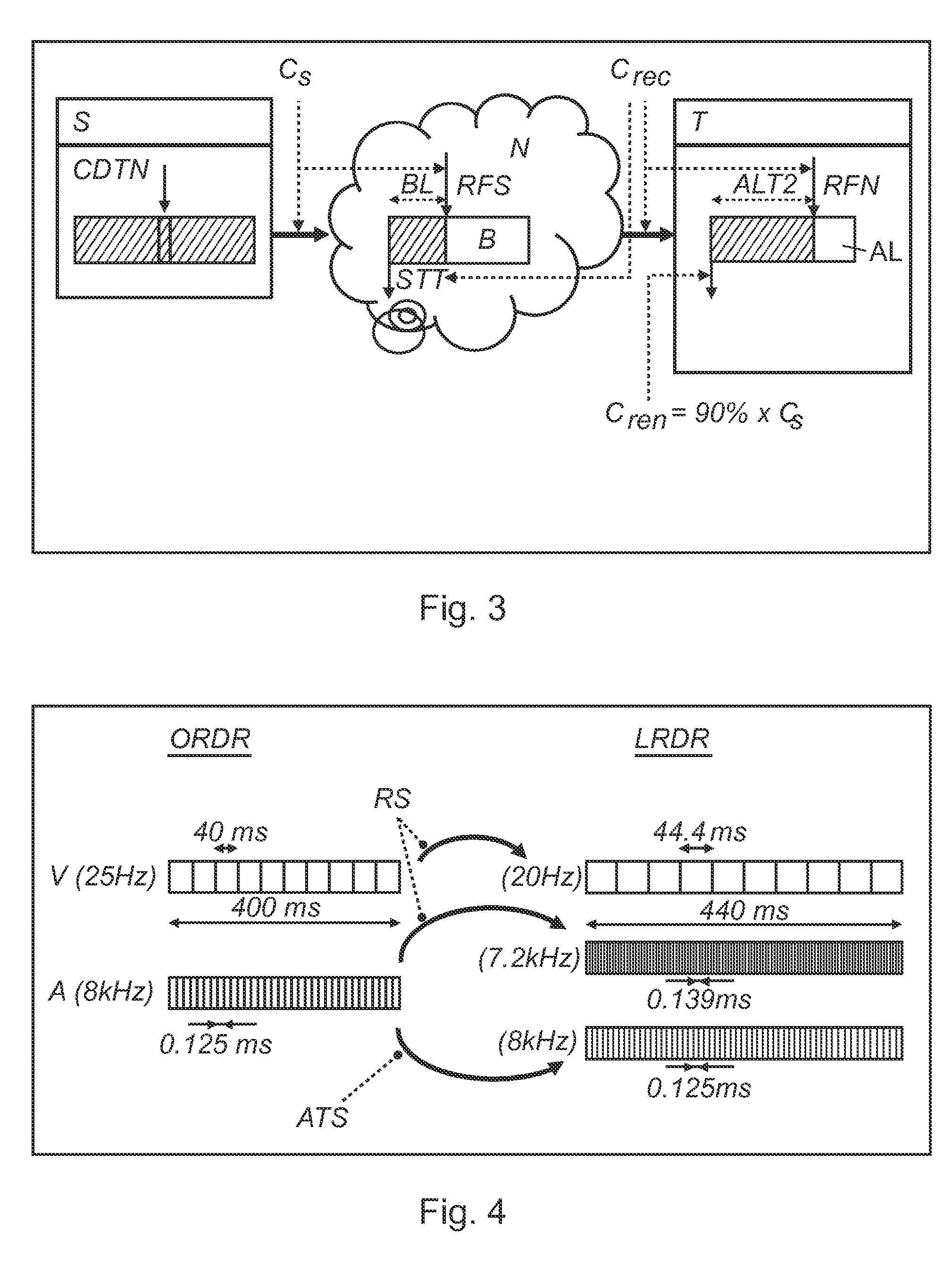
[0038]FIG. 3 shows a schematic representation of a data processing system according to a Here, the data processing system comprises a server S, a terminal T and a network N for transporting data from the server S to the terminal T. The network can comprise a buffer B with a network buffer time BL. The buffer B contains data received from the server RFS but not yet sent to the terminal STT. In FIG. 3, a situation is depicted, where the rendering of buffered data with a lower rendering rate Cren is started. The second step comprises starting the rendering with a lower rendering rate. During this phase, the terminal T starts the rendering with a low rendering rate. The server S still sends its data to the network at the same data rate CS, and the network N brings them to the terminal T which receives them at a reception data rate Crec. The main difference with step 1 is that the terminal consumes data at the rendering rate Cren. However, this rate Cren is lower than the server data ra...

third embodiment

[0040]FIG. 4 shows a schematic representation of a resampling in the method of buffering streaming data according to a The original rendering data rate ORDR is resampled to a lower rendering data rate LRDR. The lowering of the rendering data rate requires a resampling of digital content to a lower rate. Media resampling is a well known technique as will be explained with reference to FIG. 4. Video resampling (lower) can be performed by increasing the laps time between two video frames (e.g. moving from 40 ms to 44.4 ms with 10% lower rate). It does not require any complex interpolation as deviation is very limited. Moreover this processing does not create visible artifacts.

[0041]However, it should be noted that the same technique can not be used for audio, because it will lead unpleasant effects (like speeding up / down the audio tape playback). Basic resampling changes the sampling frequency and the audio pitch which creates a noticeable artifact. To avoid this artifact, the propose...


PUM


Abstract

A method of streaming data from a server (S) at a server data rate (Cs) via a network to at least one terminal at a terminal reception data rate (Crec) is provided. A streaming section from the server (S) is requested by the terminal (T). Streaming data is forwarded from the server (S) to the network (N) at a server data rate (Cs) and from the network (N) to the terminal (T) at a reception data rate (Crec). Data received from the network (N) is buffered in the terminal buffer (AL) for at least a first period. The rendering of the buffered data is initiated after the first period at a first rendering rate (Cren), which is lower than the server data rate (Cs) or the reception data rate (Crec). The first rendering data rate (Cren) is adapted according to the filling of the terminal buffer (AL) with received streaming data until the rendering data rate (Cren) corresponds to the server data rate (Cs).

Description

FIELD OF THE INVENTION[0001]The invention relates to a method for buffering streaming data in audio / video applications and a terminal device.BACKGROUND OF THE INVENTION[0002]Buffering is a common technique deployed in streaming use cases, but it may result in a poor user experience. Buffering is required in the following cases: (1) streaming session start-up (including channel zapping, from one to another one), and (2) jump / seek action initiated by the end user.[0003]An example of a data processing system including a buffer for real-time date is known from U.S. Pat. No. 6,247,072, which discloses apparatus and methods for matching data rates which is useful for a receiver receiving real-time data over a medium. Implementations feature a process establishing a buffer in a receiver; receiving source data from a source having a nominal source data rate, the received source data arriving at an incoming data rate that differs from time-to-time from the nominal source data rate; filling t...

Claims


Application Information

Patent Timeline
Patent Type & Authority Applications(United States)
IPC IPC(8): G06F15/16H04N7/173H04N7/24
CPCH04N7/17318H04N21/23406H04N21/41407H04L65/80H04N21/4402H04N21/6131H04L65/4092H04N21/44004H04L65/613H04L65/756
Inventor DELAHAYE, NICOLAS
Owner GOODIX TECH HK CO LTD
Learn More