Assembly for directing combustion gas

a technology of combustion gas and assembly, which is applied in the direction of machines/engines, stators, lighting and heating apparatus, etc., can solve the problems of increasing cold air leakage into the hot gas path through seals, reducing the amount of energy present, and requiring substantial cooling

a technology of combustion gas and assembly, which is applied in the direction of machines/engines, stators, lighting and heating apparatus, etc., can solve the problems of increasing cold air leakage into the hot gas path through seals, reducing the amount of energy present, and requiring substantial cooling

US20110203282A1Active Publication Date: 2011-08-25SIEMENS ENERGY INC

Image

  • Assembly for directing combustion gas
  • Assembly for directing combustion gas
  • Assembly for directing combustion gas

Examples


Embodiment Construction

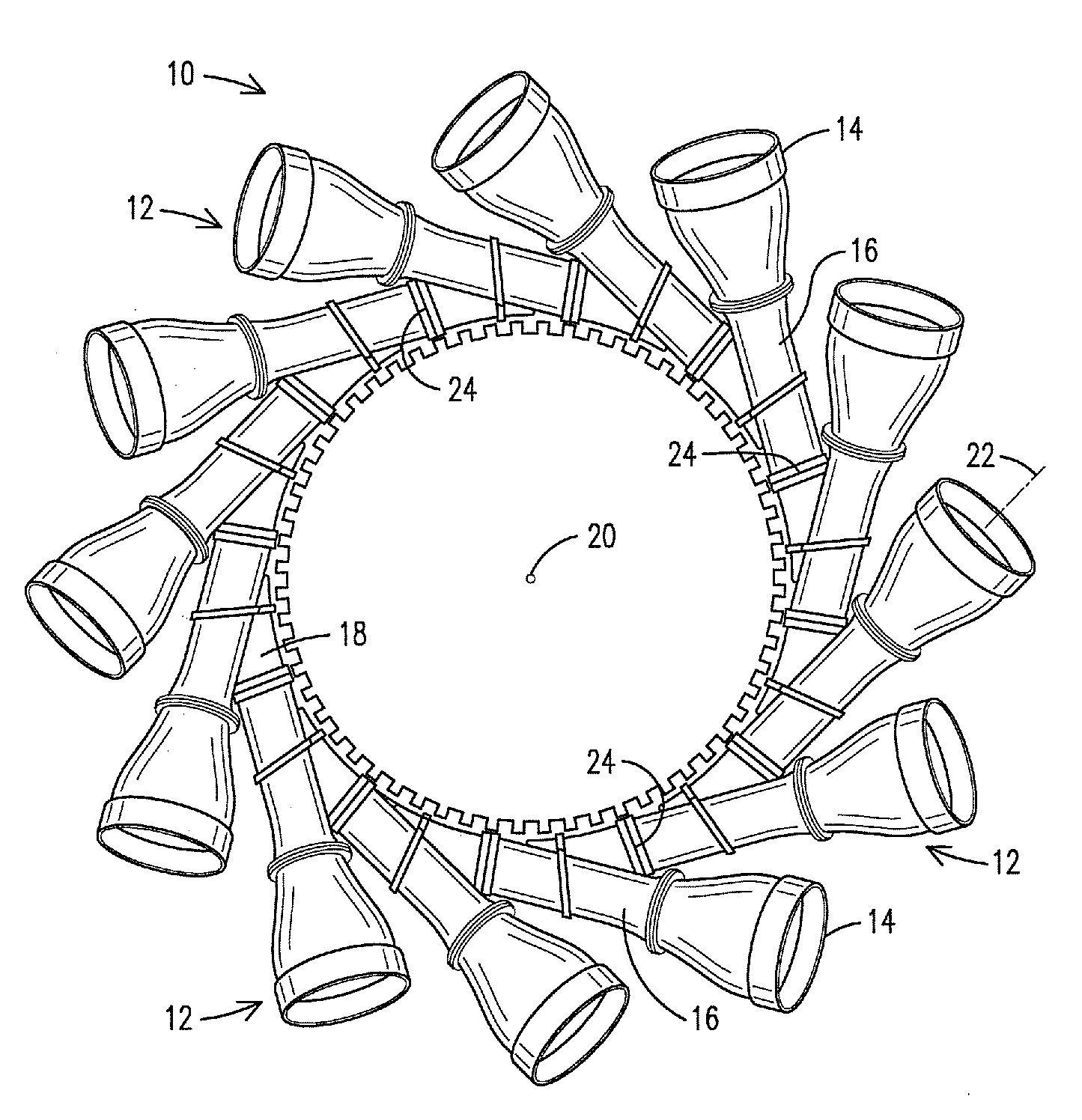
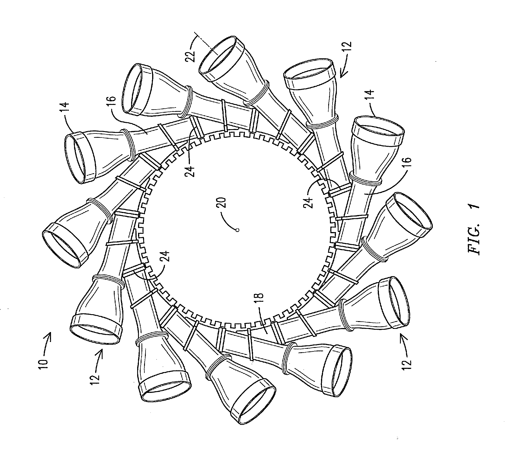
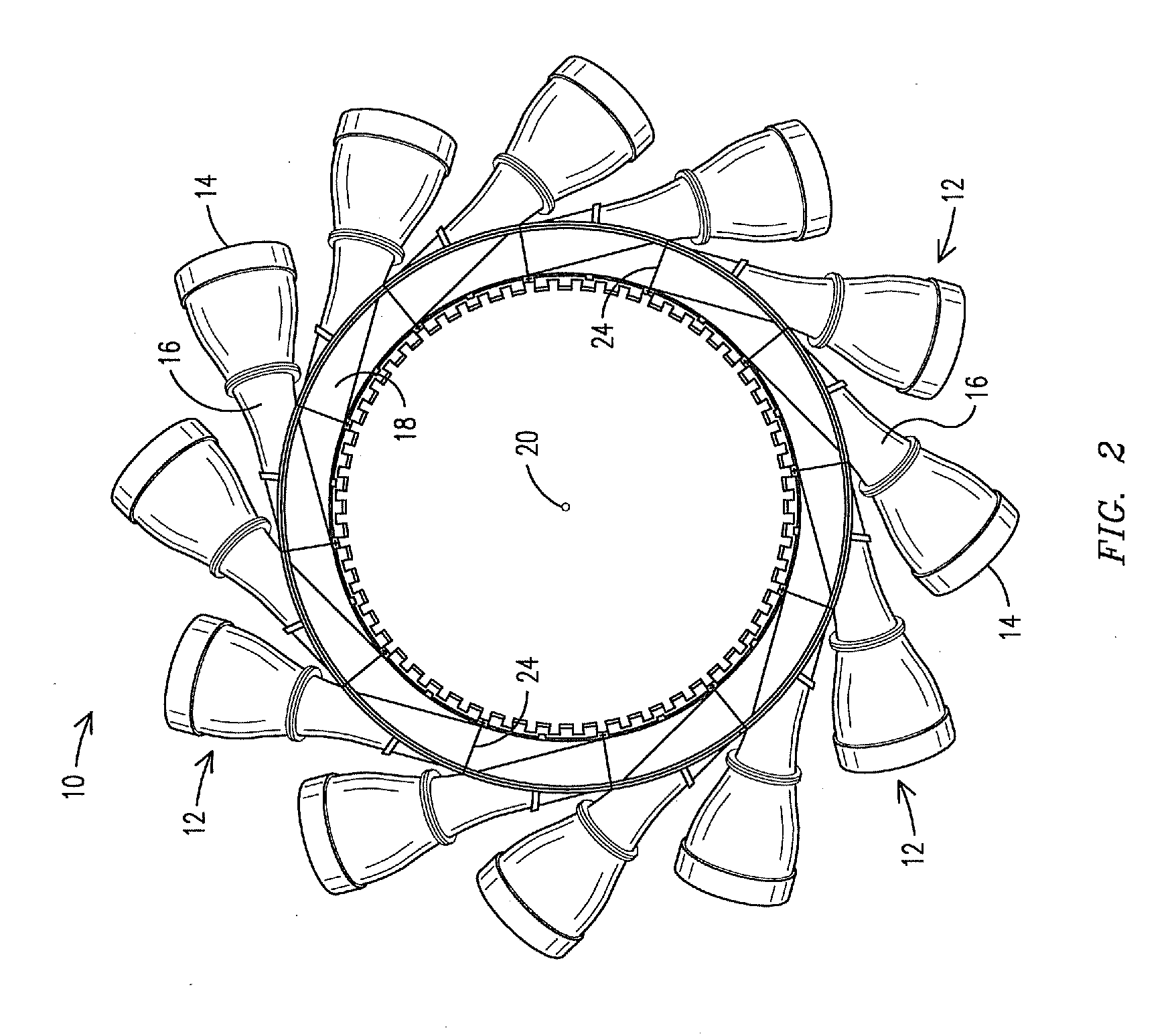
[0021]The inventors of the present system have designed an innovative arrangement, made of multiple, modular, interchangeable, flow directing assemblies. One such assembly is identified by the trademark NOVA-Ductâ„¢ by the assignee of the present invention. The combustor cans of the gas turbine combustor have been reoriented to permit the use of an assembly of components that direct individual gas flows from the combustor cans of a can annular combustor of a gas turbine combustion engine into a singular annular chamber immediately upstream and adjacent the first row of turbine blades. The inventors of the present system observed that prior configurations for delivering flows of can-annular combustors to the first row of turbine blades kept each flow separate and distinct from the other flows all the way to the first row of turbine blades. As a result, between each flow about to contact the first row of turbine blades there is a gap, or trailing edge, where there is reduced flow delive...


PUM


Abstract

An arrangement (10) for conveying combustion gas from a plurality of can annular combustors to a turbine first stage blade section of a gas turbine engine, the arrangement (10) including a plurality of interconnected integrated exit piece (IEP) sections (16) defining an annular chamber (18) oriented concentric to a gas turbine engine longitudinal axis (20) upstream of the turbine first stage blade section. Each respective IEP (16) includes a first flow path section (40) receiving and fully bounding a first flow from a respective can annular combustor along a respective common axis (22) there between, and delivering a partially bounded first flow to a downstream adjacent IEP section (42). Each respective IEP further includes a second flow path section (112) receiving a partially bounded second flow from an upstream adjacent IEP (66) and delivering at least part of the second flow to the turbine first stage blade section.

Description

[0001]This application is a continuation-in-part of U.S. patent application Ser. No. 12 / 420,149 to Wilson et al., filed 8 Apr. 2009 (attorney docket 2008P18832US01), which in turn claims priority to U.S. provisional application No. 61 / 100,853 filed 29 Sep. 2008, both of which are incorporated by reference herein.FIELD OF THE INVENTION[0002]This invention relates to gas turbine combustion engines. In particular, this invention relates to an assembly for transporting expanding gasses to the first row of turbine blades.BACKGROUND OF THE INVENTION[0003]Gas turbine combustion engines with can annular combustors require structures to transport the gasses coming from the combustors to respective circumferential portions of the first row of turbine blades, hereafter referred to simply as the first row of turbine blades. These structures must orient the flow of the gasses so that the flow contacts the first row of turbine blades at the proper angle, to produce optimal rotation of the turbine...

Claims


Application Information

Patent Timeline
25 Aug 2011
Publication
US20110203282A1
IPC
F02C3/14
CPC
F01D9/023; F23R3/425; F23R3/46; F23R3/60; F05D2250/322; F05D2250/323; F05D2250/121; F05D2250/141
Inventors
CHARRON, RICHARD C.; NORDLUND, RAYMOND S.