System and method for optimizing drilling speed

a drilling speed and optimization technology, applied in the field of system and method for optimizing drilling speed, can solve the problems of high cost of drilling process, high cost of drilling time, and high cost of operation of offshore rig, so as to increase the penetration rate, maximize the drilling effort, and increase the drilling efficiency

Active Publication Date: 2011-08-25
HALLIBURTON ENERGY SERVICES INC
View PDF6 Cites 48 Cited by
  • Summary
  • Abstract
  • Description
  • Claims
  • Application Information

AI Technical Summary

Benefits of technology

[0011]The purpose of the invention is to maximize productivity of drilling efforts. Productivity is generally determined by the ratio of rig time (time spent drilling) to NPT (Non-Productive Time); when drilling a well it is desirable to maximize this ratio because there is a cost associated with NPT whereas only rig time is a productive and useful way to spend money. Furthermore, because costs are associated with either type of time, it is desirable to minimize both forms of time, and one way to do this is to have a higher rate of penetration.
[0012]One embodiment uses selective drilling activity compression / expansion (SDACE) of historical real time data coupled with a look-ahead-of the-bit drilling simulator such as Halliburton's™ DFG™ Software with DrillAhead® Hydraulics Module. By engaging in mathematical and statistical analysis to combine these two sources of information about an ongoing drilling project, the invention can develop projections about what ECD values will be the maximum tolerable ECD values for the ongoing drilling process. Based upon what is practical for a given drilling process, the estimates can then be used to increase rate of penetration. This will then allow increased productivity by allowing a safe increase in rate of penetration.

Problems solved by technology

Needless to say, a drilling rig is a complex and expensive piece of machinery.
However, the drilling process is extremely expensive and time consuming.
The operation of an offshore rig can easily cost $500,000 per day.
Therefore, small time savings can lead to huge monetary savings.
If there is too much fluid pressure during drilling, there may be insufficient margins between formation fracture and pore pressures, which may result in damage to the formation and production difficulties.
If the pressure is low, a “blowout” can occur.
This scenario is dangerous and potentially expensive to cure.
However, there is an incentive to drill as quickly as possible, because to do so saves time and thus expense.
However, drilling faster makes it more difficult to properly respond to borehole pressure changes.
It is difficult to determine a rate of penetration that is optimally fast, and yet safe.

Method used


Image

  • System and method for optimizing drilling speed
  • System and method for optimizing drilling speed
  • System and method for optimizing drilling speed

Examples


Embodiment Construction

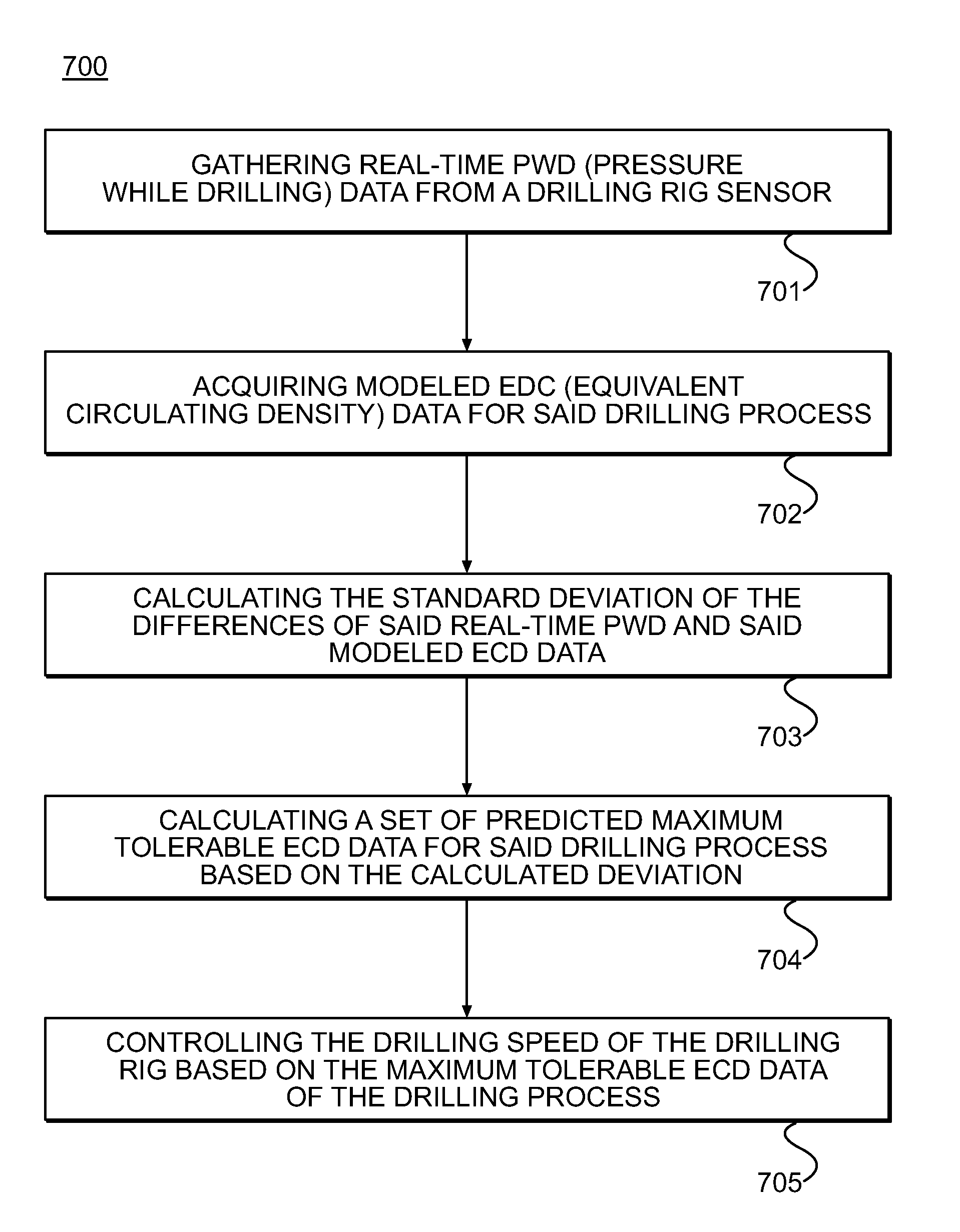
[0024]In the following description, numerous specific details are set forth in order to provide a thorough understanding of the present invention. It will be apparent, however, to one skilled in the art, that the present invention may be practiced without some or all of these specific details. In other instances, well known process steps have not been described in detail in order not to unnecessarily obscure the present invention.

[0025]In a drilling operation, tremendous pressures are generated in the borehole, which must be managed carefully. A careful balance must be struck between drilling as rapidly as is feasible, which saves precious time, and preserving the integrity of the drilling operation, by preventing fracturing or a blowout. One of the aims of the invention is to be of use in helping those involved in drilling to make decisions that will help determine an optimized drilling rate of penetration.

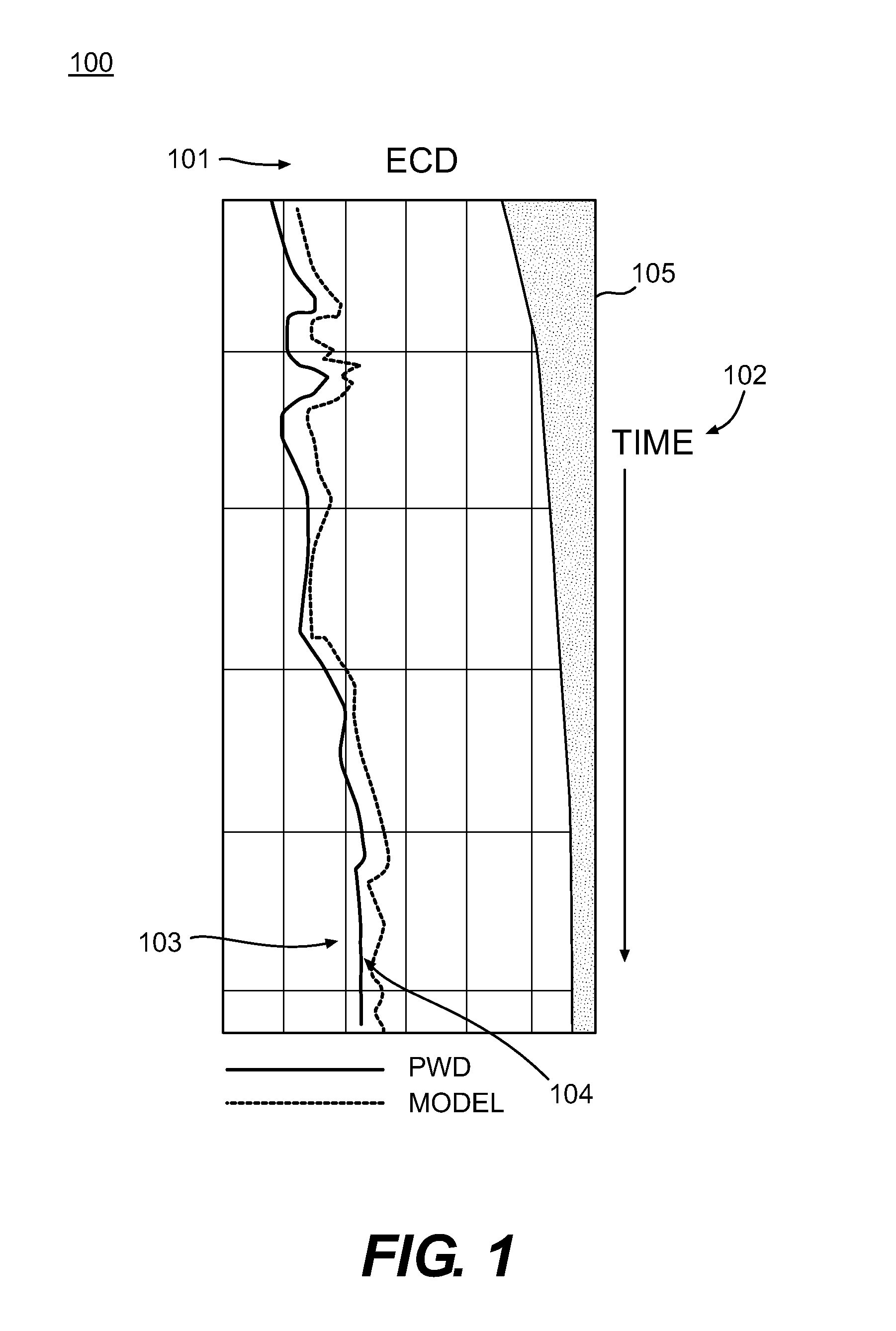
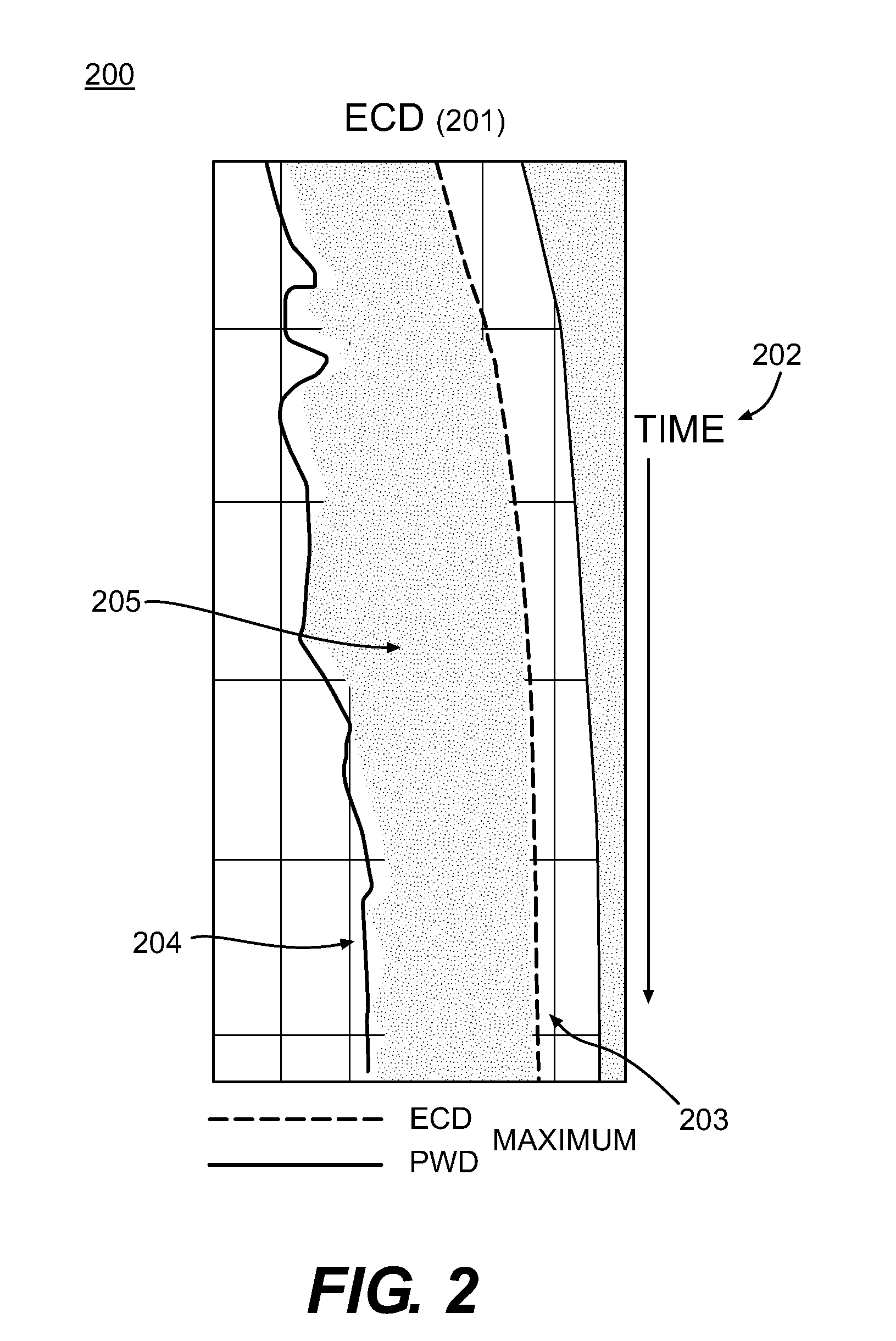
[0026]The invention does this optimization by using real-time PWD data 103 f...


PUM


Abstract

This invention presents various embodiments, including a system and a method, in which pressure-while-drilling data is gathered at a drilling rig and compared to modeled ECD pressure data related to the bore hole. The actual and modeled data are statistically analyzed to generate standard deviation data, which is used to infer information about how rapid a rate of penetration may safely be employed to optimize drilling results.

Description

CROSS-REFERENCE TO RELATED APPLICATIONS[0001]The present invention is not related to any co-pending applications.FIELD OF THE INVENTION[0002]The present invention relates to a system and method for optimizing the rate of penetration when drilling into a geological formation by utilizing data about actual and modeled borehole pressure values to determine the fastest rate of penetration at which drilling can occur safely.DESCRIPTION OF THE RELATED ART[0003]Oil and natural gas are fossil fuels that are found in certain geological formations. They are crucial as energy sources, and are used for many other chemical applications. Because of the high demand for oil and natural gas, elaborate techniques have been developed to drill into the earth's surface to reach deposits of oil and natural gas. Many times these deposits are thousands, or even tens of thousands, of feet below the surface. Also, deposits are often located beneath the ocean floor.[0004]Once a prospective deposit of oil or n...

Claims


Application Information

Patent Timeline
Patent Type & Authority Applications(United States)
IPC IPC(8): E21B7/00E21B47/00G06F17/18
CPCE21B44/02
Inventor JAMISON, DALE E.PAYLOW, KEVIN P.WILLIAMS, ROBERT L.
Owner HALLIBURTON ENERGY SERVICES INC
Why Eureka
Try Eureka