Made-to-order direct digital manufacturing enterprise

a direct digital manufacturing and made-to-order technology, applied in the direction of instruments, buying/selling/leasing transactions, data processing applications, etc., can solve the problems of inability to design and analyze, relying on solidworks software, inability to meet the needs of customers, etc., to achieve the effect of improving operational performan

Active Publication Date: 2013-08-20
KRAFTWURX INC
View PDF4 Cites 22 Cited by
  • Summary
  • Abstract
  • Description
  • Claims
  • Application Information

AI Technical Summary

Benefits of technology

[0012]In light of the preceding background, embodiments of the present invention provide methods and systems for user / customer selection, design, sale and manufacture of customized / personalized products through a streamlined and / or automated or semi-automated process combining computers, the interne, 3D modeling (also called CAD modeling), a customization interface including an interactive controls suite connected to the 3D modeling system for the purpose of allowing a user / customer to personalize or customize a product represented by a 3D geometry or multiple 3D geometries, whereby the user / customer is connected to the Cad modeling system through a website or web portal along with a 3D viewer connected to the 3D CAD geometry manipulation system for the purpose of providing design feedback and pre-purchase visualization to said user / customer accessing the system through said website or web portal, whereby said product is manifested in an automated or semi-automated fashion via additive fabrication methodologies. Embodiments of the present invention improve operational performance in a design, sale and manufacturing system to design, manufacture and sell a wide variety of products which can be adequately defined by one or more computer-based design and design implementation methods to 3D geometry manipulation where said geometry can be properly manifested by any additive fabrication technique.
[0015]Another embodiment of the invention can automate most and in some cases all, of the post-sale production operation, thereby removing most, if not all, of the human factor requirements from the system and thereby removing or minimizing the number of people involved within production environment, further optimizing the manufacturing process, maximizing productivity and minimizing labor needs.
[0016]Advantageously, embodiments of the system are conceived to be capable of assembling and modifying 3D components of a customer's unique product in increments measured in milliseconds while the product exists as a mathematically-derived 3D model or models. This is many orders of magnitude faster than any other known production system available today.
[0018]Furthermore, embodiments of the present system provide a completely flexible and scalable production operation. Deployment models may include an “in-house” model where all additive fabrication hardware resides in a single facility or at multiple facilities including diverse and / or divergent locations. Capacity within a locally deployed system can be expanded by purchasing additional Additive Freeform Fabrication hardware and adding it to the system or by taking advantage of distributed networking, the interne and available additive fabrication hardware available at other facilities. These facilities may include bureaus or other manufacturers using one or more embodiments of the present system(s).
[0021]In another embodiment, a three-dimensional model and / or a corresponding product produced (e.g., via additive fabrication) using the three-dimensional model can be provided with a custom “digital traveler” feature, which can include any manner of physical feature. This digital traveler information can thereby follow a three-dimensional model throughout the process, enabling tracking thereof, and can eventually be converted from a model to a physical portion and / or feature of a resulting object (e.g., a protruding tab, placard, appendage, or similar geometry), thereby enabling an object to be readily identified.

Problems solved by technology

Manipulating a single file that is part of an assembly in Solidworks, Inventor and other mechanical design software can impact an assembly of parts and therefore the assembly will also reflect the modifications including feedback on collisions of parts and an inability for the combination to exist physically.
Without this assembly methodology, the design and analysis would not be possible.
Furthermore, the 3D parts Stream product relies on the Solidworks software which in and of itself has limited or rigid functionality such as a very rudimentary ability to manipulate textual information.
To date, some companies are also utilizing Rapid Prototyping or Additive Freeform Fabrication hardware for limited production of products intended for functional end use directly from, or with minimal post processing, directly from the product manifestation via Additive Freeform Fabrication.
Both systems have their merits and both systems have their drawbacks.
Mechanical systems lack many of the aesthetic or Industrial Design elements of product design and manipulation software.
Industrial Design or artistic software lacks the exacting controls necessary to define a mechanical system.
The limitations of mechanical design systems extend to text information, fonts, complex or ergonomic or aesthetically please design elements.

Method used


Image

  • Made-to-order direct digital manufacturing enterprise
  • Made-to-order direct digital manufacturing enterprise
  • Made-to-order direct digital manufacturing enterprise

Examples


Embodiment Construction

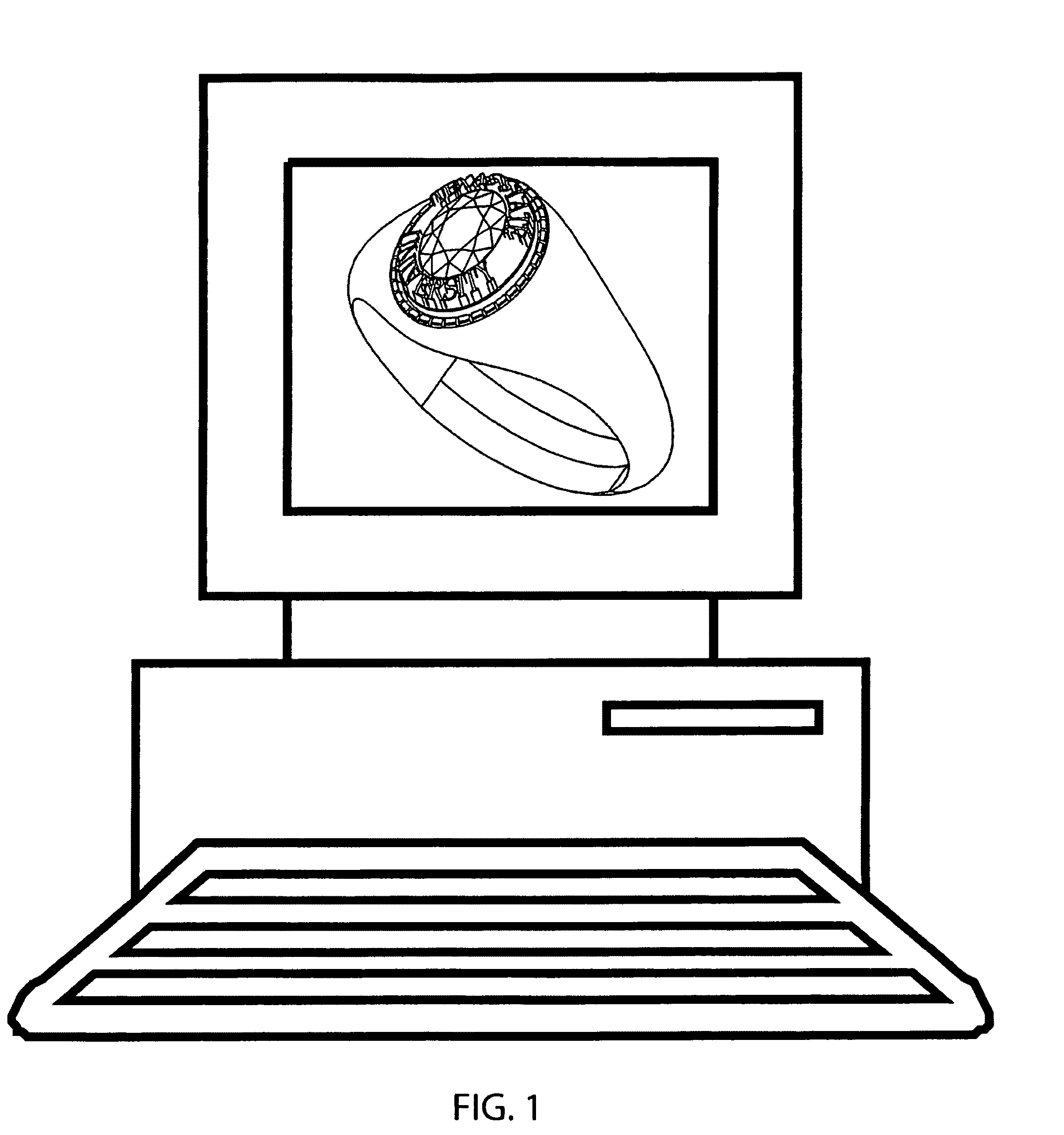
[0067]Embodiments of the present invention will now be described in detail with reference to the associated drawings, in which preferred embodiments are shown. This invention may, however, be embodied in varying forms and should not be construed as limited to the embodiments set forth herein; rather, these embodiments are provided so that this disclosure will be complete and thorough, and will fully convey the spirit of the invention.

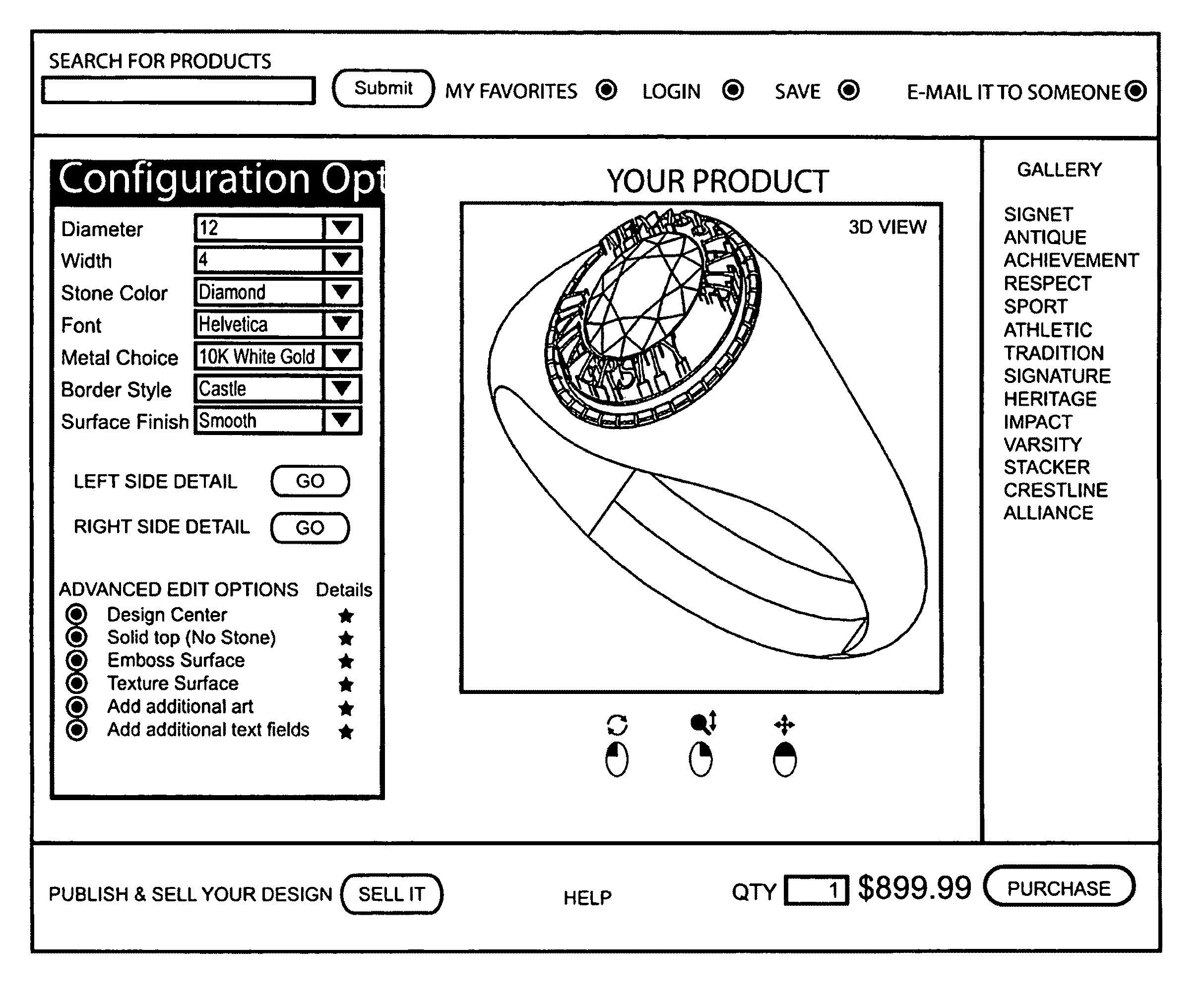
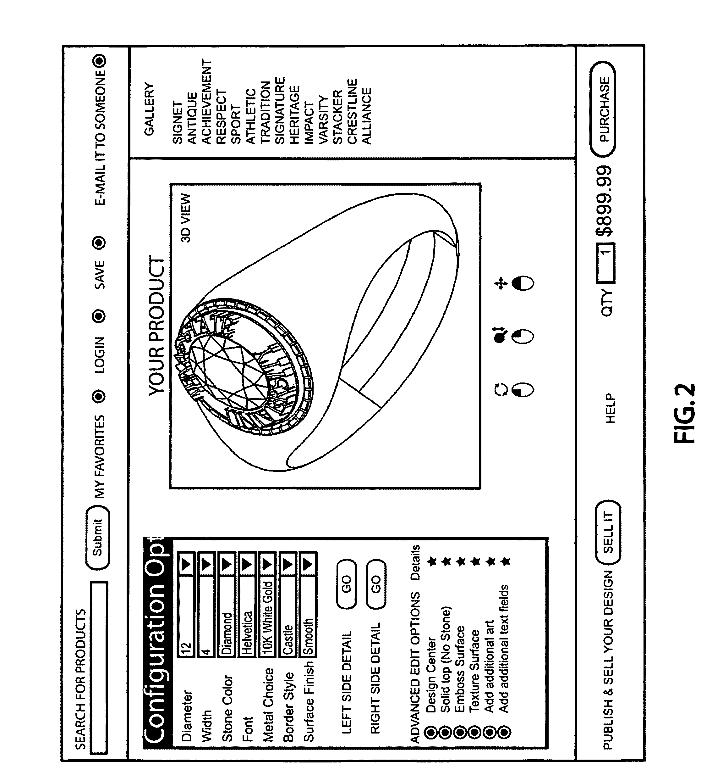
[0068]FIG. 1 represents a geospatial / 3D geometry system, commonly referred to by someone skilled in the art as a computer aided design or geospatial design and configuration system or CAD system which for the intent of disclosure, is intended to be defined as a means to design a product which may be made available for customization / personalization within the present invention.

[0069]In one embodiment, the system deploying the method of the present invention, shall allow for the input of any geospatial / 3D geometry design produced in a plurality of design ...


PUM


Abstract

Methods and systems for designing and producing a three-dimensional object selection of a base three-dimensional object from a customer device. A base three-dimensional model corresponding to the object is displayed on the customer device, and one or more custom modifications are received. A modified three-dimensional model corresponding to the modified object is prepared and displayed. Once confirmation to produce the modified object is received, data corresponding to the modified three-dimensional model is transmitted to a manufacturing device for production of the object, using the data to do so, such that the object corresponds directly to the modified three-dimensional model.

Description

CROSS REFERENCE TO RELATED APPLICATIONS[0001]The present application claims priority to the co-pending U.S. patent application having the Ser. No. 11 / 750,499, filed May 18, 2007, the entirety of which is incorporated herein by reference.FIELD OF THE INVENTION[0002]The present invention relates to the design, sale and manufacture of made-to-order or mass-customized products. More specifically to a computer-based method and system for customer-driven design, sale and manufacturing of unique or custom-made product(s) exclusively through a highly efficient sales & manufacturing system which advantageously combines key elements of computer aided design methodologies, the interne and Additive Fabrication methodologies to personalize or customize said products.BACKGROUND OF THE INVENTION[0003]The customization of durable goods products is a desirable characteristic that many retail markets would enjoy being able to broadly utilize and many consumers would enjoy broadening their product sel...

Claims


Application Information

Patent Timeline
Patent Type & Authority Patents(United States)
IPC IPC(8): G06Q30/00
CPCG06Q30/06G06Q30/0621B33Y50/00B33Y80/00
Inventor NORMAN, BRYAN C.
Owner KRAFTWURX INC
Why Eureka
Try Eureka