Synchronous Induced Wind Power Generation System

a wind power generation system and synchronous technology, applied in the direction of electric generator control, machines/engines, mechanical equipment, etc., can solve the problems of inability to achieve large-scale adoption of wind power as an alternative means, difficulty in repair and maintenance of large systems, and limited effect of conventional wind power generation systems

Inactive Publication Date: 2011-08-25
SKALA JAMES A
View PDF14 Cites 18 Cited by
  • Summary
  • Abstract
  • Description
  • Claims
  • Application Information

AI Technical Summary

Benefits of technology

[0027]In another preferred embodiment, the synchronous induced wind power generation of the first embodiment above is provided, further comprising one or more controllable, pivotable air bypass doors disposed in or adjacent to the first end and second end of the outer shell of the turbine / generator units, which may be operated in such a manner as to reduce excess air flow through the turbine-generator unit.

Problems solved by technology

However, the effectiveness of conventional wind power generation systems have been limited by various difficulties such as, for example, the inconsistency of the wind, appropriate locations for placement of wind power generation system far from load centers and the problems of long distance transmission of power, difficulty in repair and maintenance of large systems, etc.
These difficulties have inhibited large scale adoption of wind power as an alternate means of energy.
However, the longer blades require a supporting tower having a corresponding increased height and size.
Further, such large size blades prevent placement of conventional wind turbines within urban / suburban environments where the greatest demand for energy exists.
Moreover, the large wind turbines are more subject to damage from high winds, as well as structural fatigue failures.
Namely, the blades are subject to fatigue by encountering significantly higher wind loads at the top of the arc of rotation, followed a second later by lower velocity wind loads, which culminate at the bottom of the arc of rotation by a big thud as the blade passes the supporting column, where the flow of air is disrupted.
And, the large blades frequently strike birds, resulting in conflict with environmental groups and government regulations.

Method used


Image

  • Synchronous Induced Wind Power Generation System
  • Synchronous Induced Wind Power Generation System
  • Synchronous Induced Wind Power Generation System

Examples


Embodiment Construction

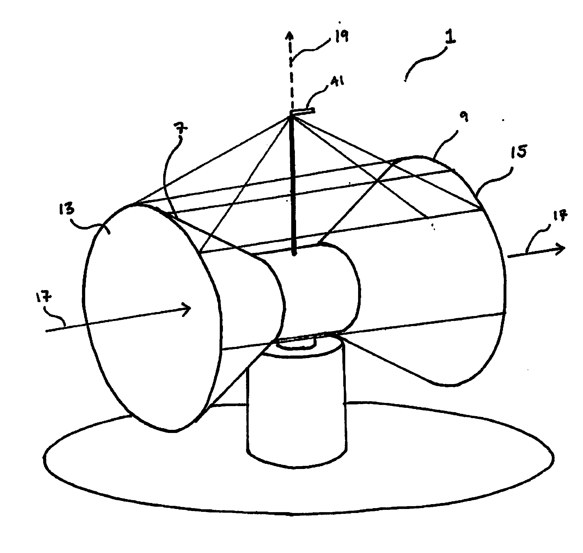
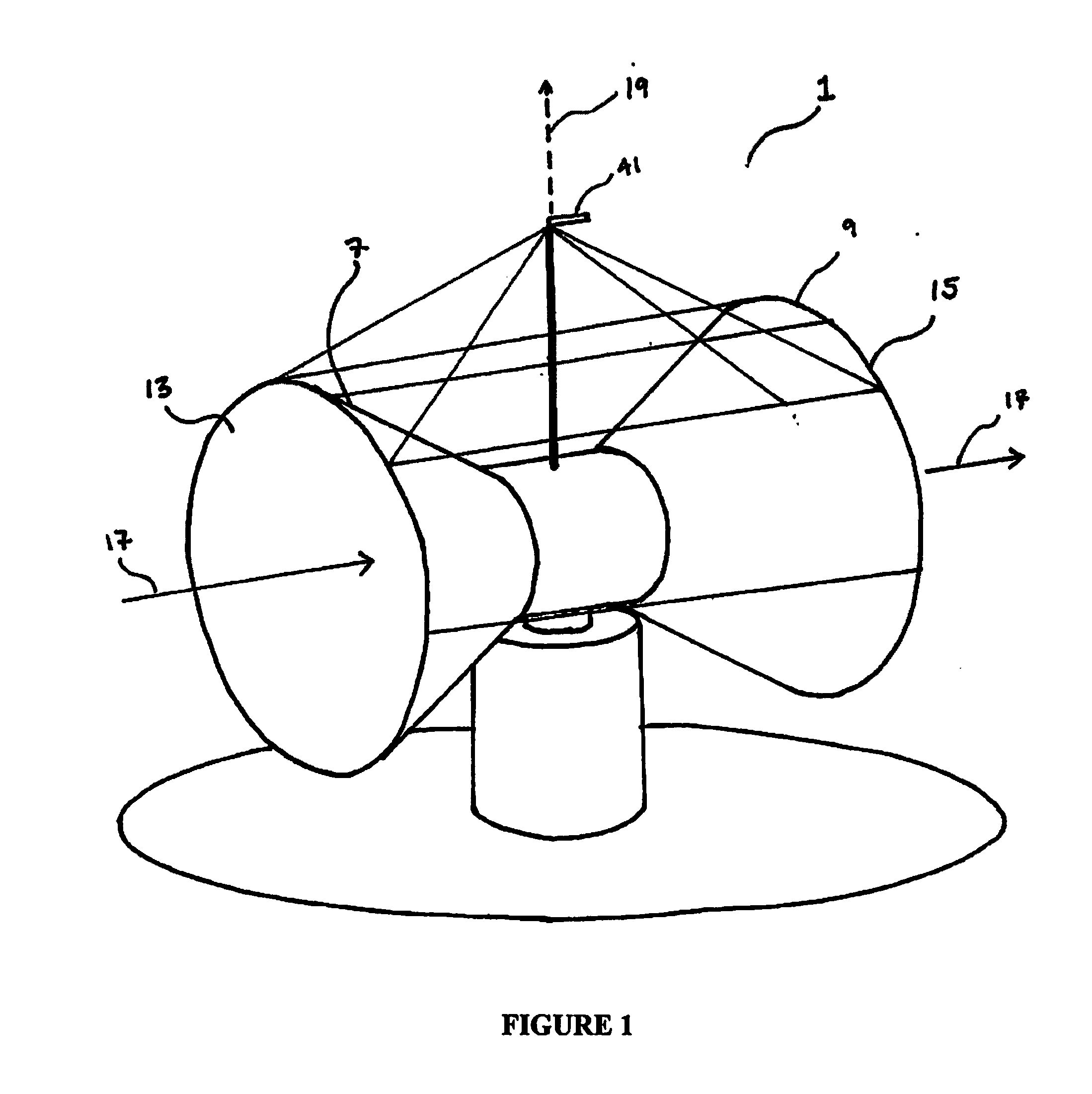
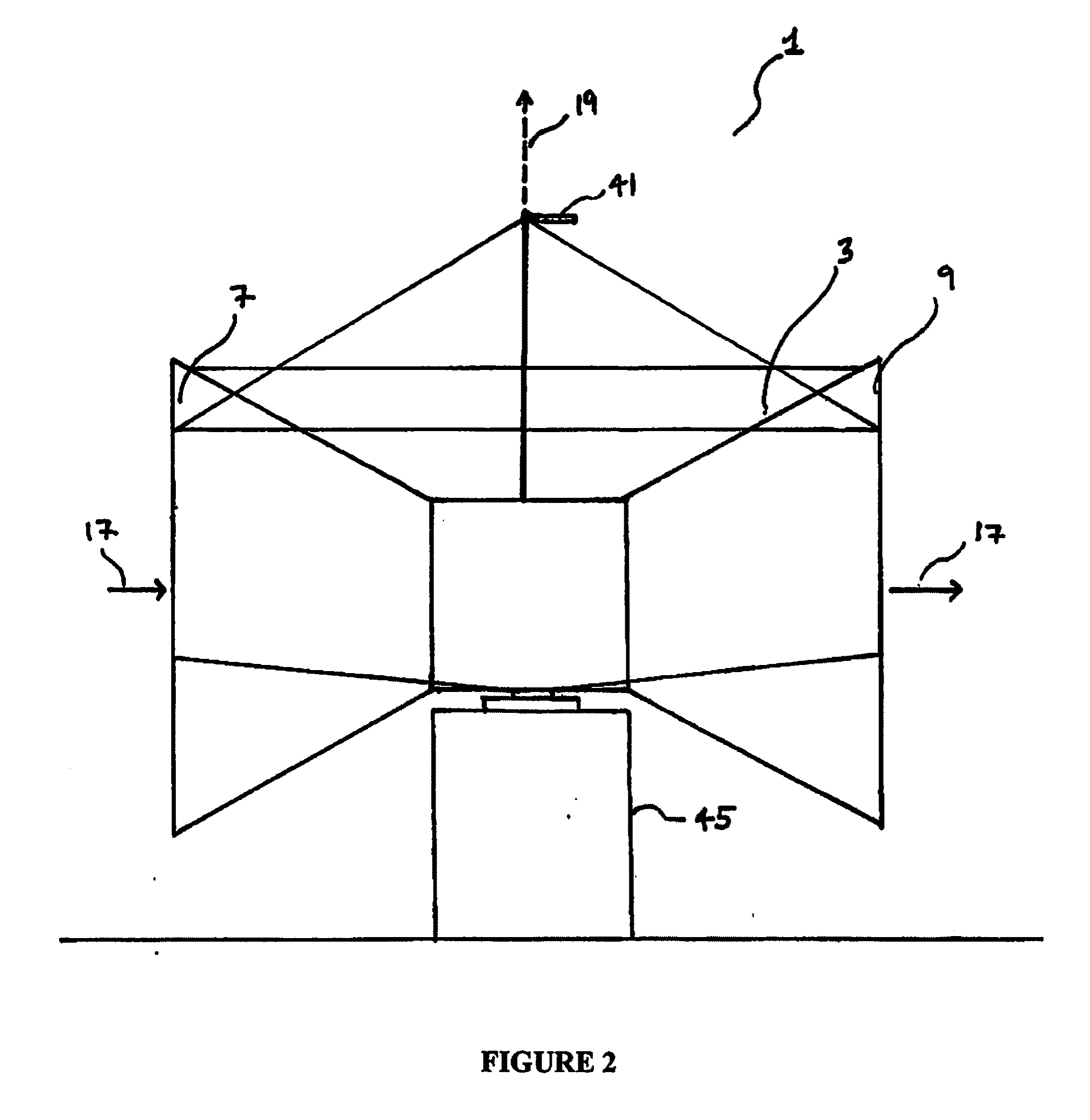
[0034]As illustrated in FIGS. 1-3, the present invention provides a synchronous induced wind power generation system 1 comprised generally of a turbine-generator section 3, a turbine-generator unit 21 disposed therein, a direction orientation means 45 in movable connection with the turbine-generator section 3, and a control system 33 operable to control the entire system 1 based on, for example, wind velocity, wind direction, external load characteristics, power requirements, etc.

[0035]Specifically, as shown in FIGS. 1 and 2, the turbine-generator section 3 is comprised of an outer shell 5 having a first end 7, a second end 9 opposite the first end 7, and an interior area 11 disposed there between. A first orifice 13 is disposed at the first end 7, a second orifice 15 is disposed at the second end 9, a wind flow axis 17 extends from the first orifice 13 to the second orifice, and an axis of rotation 19 disposed perpendicular to the wind flow axis 17. The turbine-generator section 3 ...


PUM


Abstract

A synchronous induced wind power generation system is provided, which is comprised of a rotatable turbine-generator section and a control system operable to rotate same in a direction corresponding to optimal wind conditions. The turbine-generator section has a horizontally disposed turbine therein in an interior area thereof, and orifices formed at either end thereof, with wider areas than the interior area, so as to form a funnel-like shape at either of the turbine-generator section. These funnel-shaped sections optimally funnel wind to the turbine, which is connected to a synchronous generator that runs at synchronous speed with an external power line in connection therewith. Further, turbine brakes are employed to modulate turbine power and speed, and the control system is operable to orient the turbine-generator section with respect to the direction of the wind and generation of power via control of the turbines and synchronous generator, and via receipt of sensor / detector data received from a plurality of sensors / detectors in communication therewith.

Description

BACKGROUND OF THE INVENTION[0001]1. Field of the Invention[0002]A synchronous induced wind power generation system is provided, which is comprised of a rotatable turbine-generator section and a control system operable to rotate same in a direction corresponding to optimal wind conditions. In particular, a wind power generation system is provided having a turbine-generator section with a horizontally disposed rotating shaft therein connecting the turbine to the generator, orifices formed therein so as to optimally funnel wind over the turbines, turbine brakes to control the rotational speed of the turbines and the shaft power delivered to the generator, and a control system operable to orient the turbine-generator section with respect to the direction of the wind and generation of power via control of the turbine brakes and the synchronous generator.[0003]2. Description of the Related Art[0004]Wind as an alternate motive force for generating electricity has long provided an attractiv...

Claims


Application Information

Patent Timeline
Patent Type & Authority Applications(United States)
IPC IPC(8): F03D7/00F03D9/00
CPCF03D1/04F03D7/0204F03D7/0268F05B2220/70642Y02E10/725F05B2260/903F05B2270/32F05B2270/321Y02E10/723F05B2240/133Y02E10/72F03D80/00
Inventor SKALA, JAMES A.
Owner SKALA JAMES A
Why Eureka
Try Eureka