System and method for hybrid geometry feed horn

a technology of hybrid geometry and feed horn, which is applied in the direction of waveguide horn, antenna, electrical equipment, etc., can solve the problems of inability to communicate with feed horns within single feed horns, inability to make smooth wall ka-band feed horns, and inability to communicate with conventional feed horn assemblies suitable for single-piece casting

Active Publication Date: 2011-08-25
VIASAT INC
View PDF22 Cites 31 Cited by
  • Summary
  • Abstract
  • Description
  • Claims
  • Application Information

AI Technical Summary

Benefits of technology

[0005]In accordance with various aspects of the present invention, a device, system and method related to a hybrid geometry feed horn is presented. In one exemplary embodiment, a hybrid geometry feed horn includes a first portion of the feed horn comprising a dual mode geometry and a second portion of the feed horn comprising an axial corrugation geometry. In one exemplary embodiment the feed horn is configured to operate in a plurality of separate frequency bands and a plurality of s

Problems solved by technology

Historically, high performance simultaneous multiple low and high frequency, dual mode, feed horn communication has not been possible within a single feed horn that may be fabricated using low cost methods such as conventional single-piece casting.
Conventional single-piece casting has often imposed design constraints that have discouraged the use of such techniques for feed horns of the type discussed above.
Additionally, conventional feed horn assemblies suitable for single-piece casting have not been able to communicate using HE mode, TE mode and/or TM mode over wide bandwidths.
For example, it is believed that it is not possible to make a smooth wall Ka-Band feed horn with solely a dual mode architecture that can operate over two frequency bandwidth segments

Method used


Image

  • System and method for hybrid geometry feed horn
  • System and method for hybrid geometry feed horn
  • System and method for hybrid geometry feed horn

Examples


Embodiment Construction

[0020]While exemplary embodiments are described herein in sufficient detail to enable those skilled in the art to practice the invention, it should be understood that other embodiments may be realized and that logical electrical and mechanical changes may be made without departing from the spirit and scope of the invention. Thus, the following detailed description is presented for purposes of illustration only.

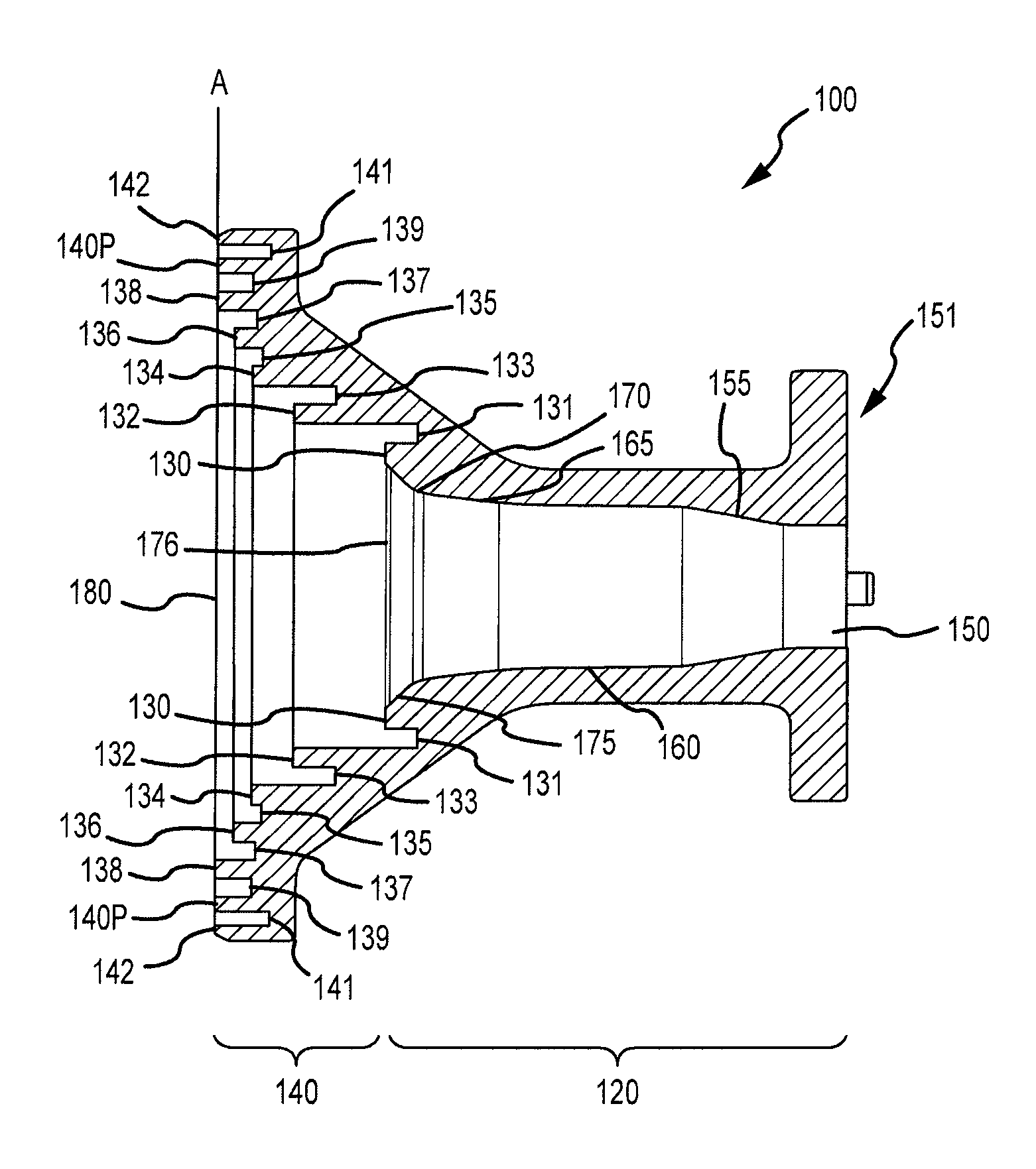
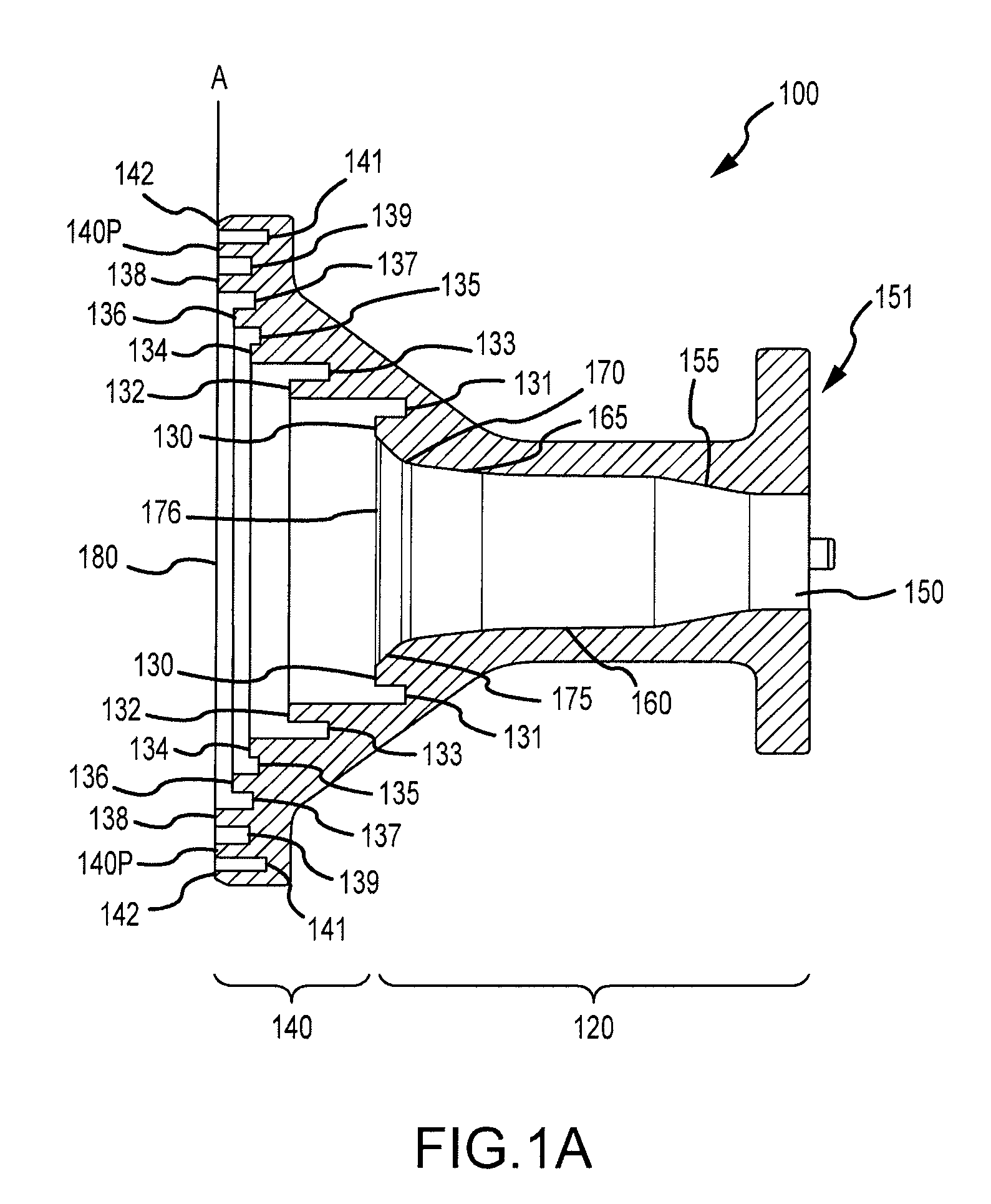
[0021]In accordance with an exemplary embodiment of the present invention, a hybrid feed horn is formed by combining at least some features from both a dual mode geometry feed horn and at least some features from an axial type corrugation geometry feed horn. The hybrid feed horn may be fabricated using low cost methods such as conventional single-piece casting. This monolithic construction may facilitate lower losses as well as facilitate construction by reducing dimensional tolerance issues. In an exemplary embodiment, the hybrid feed horn may have a short axial length. For e...


PUM

PropertyMeasurementUnit
Frequencyaaaaaaaaaa
Frequencyaaaaaaaaaa
Frequencyaaaaaaaaaa

Abstract

A feed horn and systems and methods of making and using the feed horn are presented. Exemplary feed horns include a first portion comprising a dual mode geometry and a second portion comprising an axial corrugation geometry. The feed horn may operate simultaneously in a plurality of separate frequency bands (e.g., from about 18.3 GHz to about 20.2 GHz and from about 29.1 GHz to about 30.0 GHz) and a plurality of separate waveguide modes (e.g., TE11, TM11 or HE11 modes); simultaneously operating over two bandwidth segments of at least 1900 MHz that are separated by at least 5000 MHz. The feed horn may have a short axial length (e.g. less than 4 wavelengths at 18.3 GHz), and it may be configured to operate in a prime fed offset reflector antenna system. In addition, the feed horn may be formed as a single piece via a single casting pull.

Description

FIELD OF INVENTION[0001]The application relates to systems, devices, and methods for conveying radio waves. More particularly, the application relates to a hybrid horn antenna system configured to communicate over a wide frequency bandwidth and configured to accept multiple separate frequencies and multiple separate modes, where the hybrid horn antenna may be fabricated using low costs methods such as casting.BACKGROUND OF THE INVENTION[0002]A feed horn may convey radio frequency signals to / from a remote location (such as a satellite). Historically, high performance simultaneous multiple low and high frequency, dual mode, feed horn communication has not been possible within a single feed horn that may be fabricated using low cost methods such as conventional single-piece casting. Conventional single-piece casting has often imposed design constraints that have discouraged the use of such techniques for feed horns of the type discussed above. Additionally, conventional feed horn assem...

Claims


Application Information

Patent Timeline
IPC IPC(8): H01Q13/02H01Q13/00H01Q5/00
CPCH01Q13/0216H01Q5/00Y10T29/49016H01Q13/025H01Q13/0291H01Q13/0208
Inventor RUNYON, DONALD LAWSONKOKOTOFF, DAVID MARK
Owner VIASAT INC
Why Eureka
Try Eureka