Method and apparatus for low-light imaging enhancement

a low-light imaging and enhancement technology, applied in the field of imaging, can solve the problems of amplifying electronic and photonic noise, images captured in low-light can appear noisy and contain less high-frequency content, images captured with flash can produce harsh flat appearance, etc., to maximize an objective quality criterion and enhance low-light imaging

Active Publication Date: 2011-08-25
QUALCOMM INC
View PDF21 Cites 28 Cited by
  • Summary
  • Abstract
  • Description
  • Claims
  • Application Information

AI Technical Summary

Benefits of technology

[0030]At block 215, a combined image may be calculated based on the detected image data. One advantage of the invention may be to utilize details from image data of either of the ambient image and illuminated / flash image, in contrast to conventional methods which only utilize image detected with flash. As will be discussed in more detail below with respect to FIG. 5, combined image data may be calculated to create an optimal combined image to include illumination details associated with image data of the ambient image and illuminated image, and to maximize detail and minimize noise. In one embodiment, image data for the combined image is selected to maximize an objective quality criterion of the combined image. For example, the objective quality criterion may relate to signal to noise ration.
[0031]In certain instances, combined, image data may appear unnatural or flat. Accordingly, combined image data may be blended with image data associated with artificial illumination to generate a continuous flash effect in one embodiment. For example, enhancement of image data to correct for a flat or unpleasant appearance of artificial light on image details. In one embodiment, process 200 may include determine a compositing mask at block 220 to blend image data associated with the illuminated image with combined image data at block 225. In order to selectively correct for unpleasing areas of image data, portions of the image data which do not have a pleasing appearance may be replaced to generate an optimal tone rendered result at block 225. Thus, blending image data at block 225 can localize the correction only to required regions. Based on the blending of image data, the digital imaging device may store a tone rendered result at block 230.
[0032]Referring now to FIG. 3, a process is depicted for low-light imaging enhancement according to another embodiment. Process 300 may be performed by a processor of an imaging device (e.g., imaging device 100) according to one embodiment. Process 300 may allow for aborting enhancement of image data when alignment of detected images may not be performed, or when said alignment process fails. Process 300 may be initiated by detecting image data at block 305, such as image data associated with ambient light of a scene and image data associated with artificial lighting of a scene, such as a flash emitted by the imaging device. At block 310, the processor of the imaging device may align image data. The processor may then check the alignment of the image data at decision block 315. When alignment of the image data produces an alignment error (e.g., “YES” path out of decision block 315) process 300 may abort the enhancement of detect image data at block 320. For example, the process 300 processor may abort image enhancement when it is detected that significant areas of the image exhibit local misalignment as will be discussed in more detail below with respect to FIG. 4. In certain embodiments, process 300 may display a message to a user of the imaging device that captured image data resulted in an error. Alternatively, one of the source images (such as the flash image), may substitute the result of the process 330 in these instances. Alternatively, or in combination, the imaging device may prompt the user to capture another image of the scene. Accordingly, process 300 may capture image data as depicted at block 305, such as third and fourth additional frames.
[0033]When image data does not result in an alignment error (“NO” path out of decision block 315), process 300 may then create a combined image at block 325. Process 300 may then calculate a tone rendered image at block 330 based, at least in part, on image data detected at block 305.
[0034]Referring now to FIG. 4, a process is depicted for detecting alignment errors according to one embodiment. Because image data employed for image enhancement (e.g., image data detected at blocks 205 and 305) is not captured at the same instant, motion of the imaging device, such as user hand shake, can cause undesirable artifacts in combined image data. In one embodiment, image data is aligned by calculating motion of image content between frames. Inverse motion may be applied to one image frame in order to compensate for motion according to one embodiment.
[0035]Local alignment errors may be caused when an object in a scene is moving quickly. In certain instances, alignment of image data for global motion, such as camera shake, may not compensate for local movement. According to one embodiment, local motion may be detected by searching for an area of the image which includes motion after compensation for global motion. When significant areas in the image exhibit local misalignment, enhancement of image data may be aborted or the region of image data may be replaced. Process 400 provides for estimation of motion and a global transformation. In one embodiment, process 400 may estimate global transformation based on a statistical estimation algorithm, such as Random Sample Consensus Algorithm (RANSAC).

Problems solved by technology

Applying high gain, however, amplifies electronic and photonic noise in additional to amplifying the image signal.
As a result, images captured in low-light can appear noisy and contain less high frequency content (e.g., details) due to amplification of the noise.
However, images captured with flash can produce a harsh flat appearance resulting from the direct lighting.
However, these solutions are not well suited for compact imaging devices, like portable cameras only having a single flash, wherein the flash is usually embedded in the body and is not adjustable.
These methods, however, take details undiscernibly from the image data resulting in the introduction of additional digital noise to the scene in parts of where the flash image is very dark or (conversely) over-saturated.

Method used


Image

  • Method and apparatus for low-light imaging enhancement
  • Method and apparatus for low-light imaging enhancement
  • Method and apparatus for low-light imaging enhancement

Examples


Embodiment Construction

Overview and Terminology

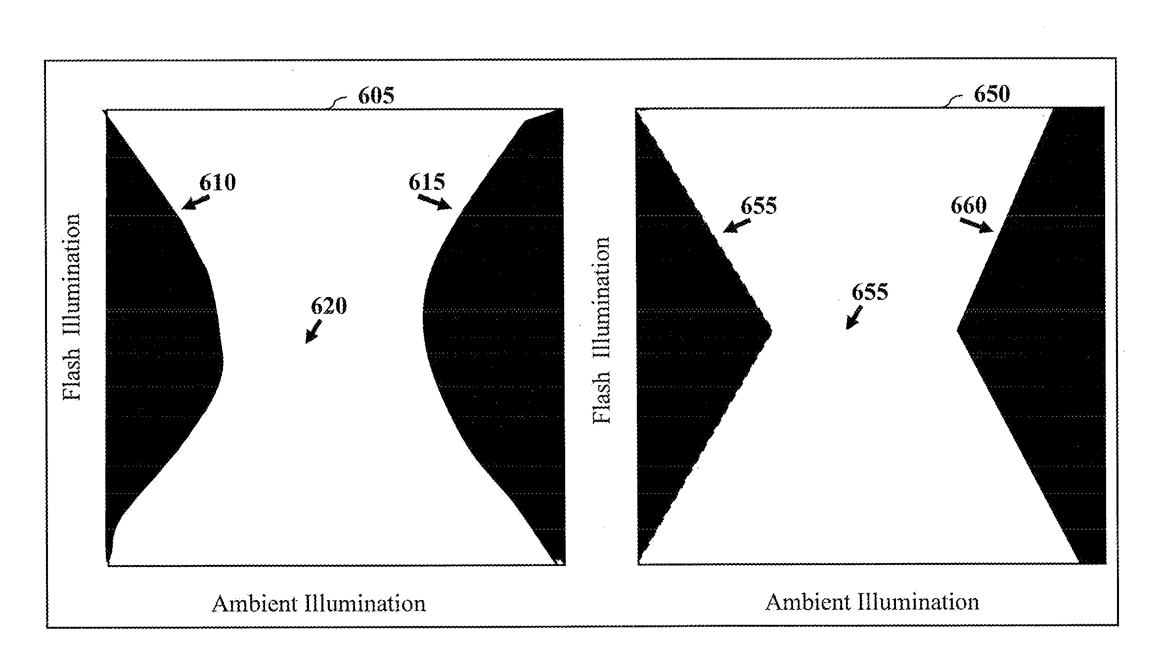
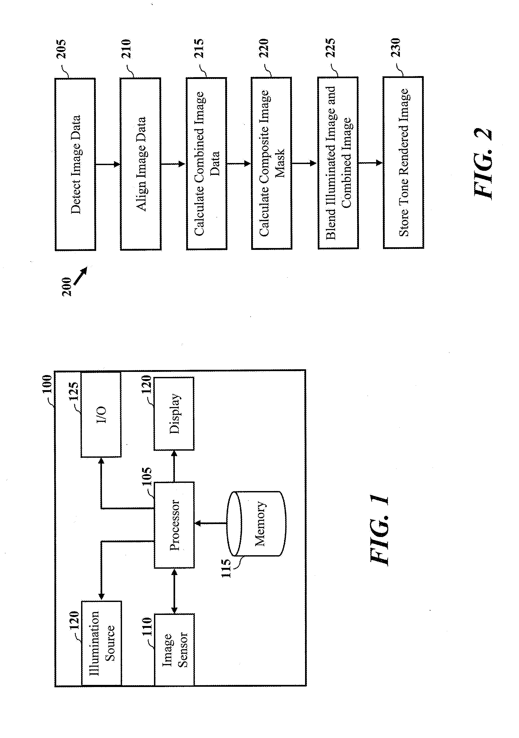
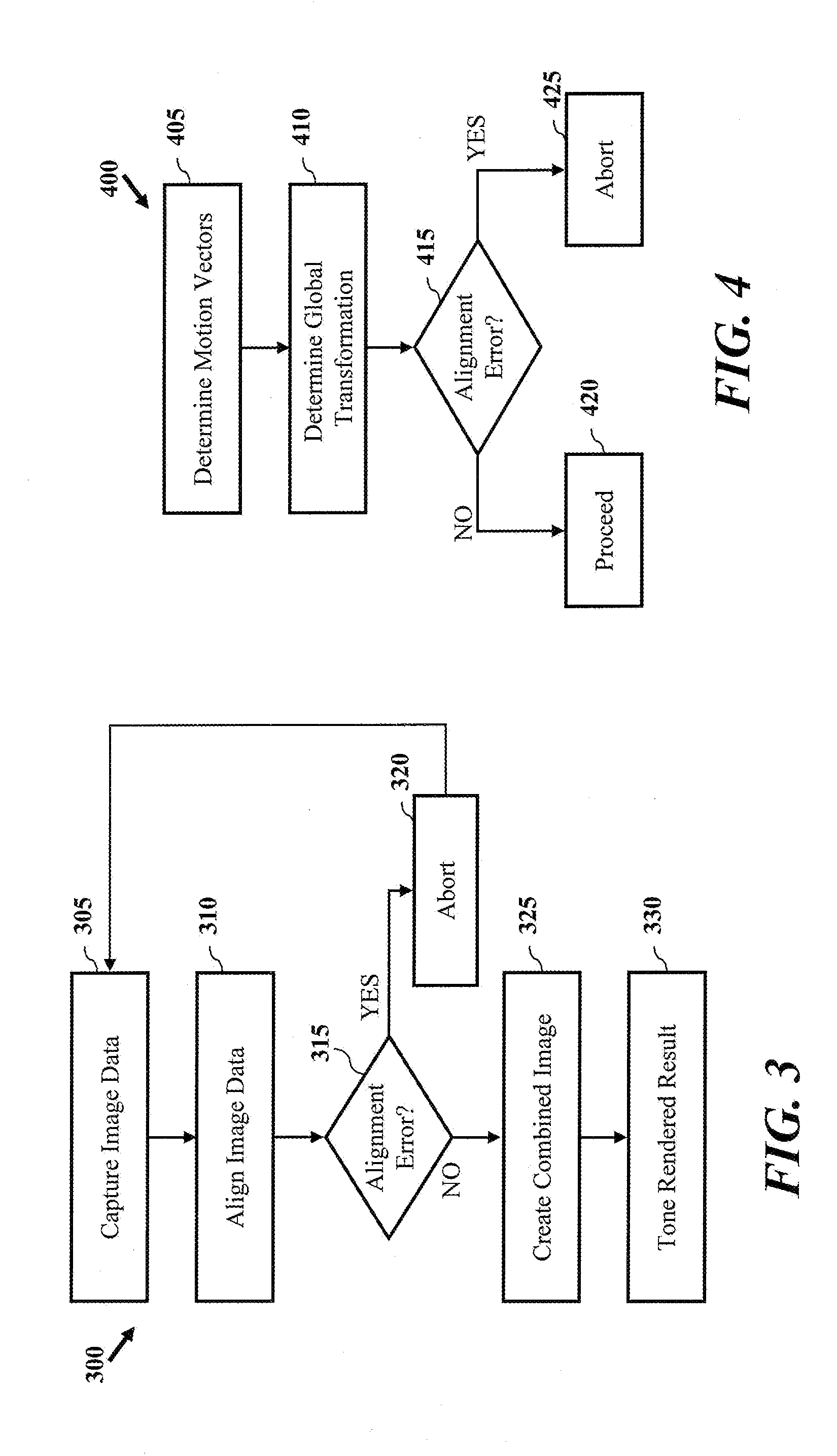
[0016]One aspect of the present invention relates to enhancing low-light image data capture. In one embodiment, process is provided for enhancement including detecting image data associated with ambient lighting of a scene, and detecting image data with artificial illumination or lighting (e.g., flash) of a scene. The process may include alignment of the captured image data, and calculation of a composite image. The process may further include determining an image parameter, such as a composite mask, and blending image data associate with image data captured with artificial light, and the composite image based on an image parameter, such as a masking image. As such, details may be selected from one or more of the image data captured using ambient light and image data captured based on artificial illumination. In addition, tone rendered blending of composite image data may be employed to optimize combination of image data.

[0017]In another embodiment, an imagin...


PUM


Abstract

A device and methods are provided for low-light imaging enhancement by a digital imaging device. In one embodiment, a method includes detecting an image associated with ambient lighting of a scene, detecting an image associated with artificial lighting of the scene, aligning the image associated with ambient lighting relative to the image associated with artificial lighting based on a motion parameter of ambient lighting image data and artificial lighting image data, and calculating data for a combined image based on aligned ambient lighting image data and artificial lighting image data, wherein image data for the combined image is selected to maximize an objective quality criterion of the combined image. The method may further include determining an image parameter based on ambient lighting image data, blending image data associated with the artificial lighting and the combined image based on the image parameter to generate a tone rendered image.

Description

CROSS-REFERENCE TO RELATED APPLICATION[0001]This application claims the benefit of U.S. Provisional Application No. 61 / 306,893, filed Feb. 22, 2010.FIELD OF THE INVENTION[0002]The present invention relates in general to methods for imaging and in particular to enhancing low-light image capture.BACKGROUND[0003]Conventional methods for image capture in low-light typically employ one or more corrective measures to properly detect a scene. For example, handheld cameras typically apply high gain to image data captured of a low-light scene. Applying high gain, however, amplifies electronic and photonic noise in additional to amplifying the image signal. As a result, images captured in low-light can appear noisy and contain less high frequency content (e.g., details) due to amplification of the noise. One conventional solution is to introduce additional light to a scene by activating a flash of the camera during capture. This will result in a brighter scene, and can allow for gain to be lo...

Claims


Application Information

Patent Timeline
Patent Type & Authority Applications(United States)
IPC IPC(8): H04N5/235
CPCH04N5/23229H04N5/2354G06T2207/10152G06T5/50G06T2207/10016G06T5/008H04N23/80H04N23/74
Inventor LEVY, NOAM
Owner QUALCOMM INC
Why Eureka
Try Eureka