athermal lens device

a lens and athermal technology, applied in the field of athermal lens devices, can solve the problems of large image blur due to the shift of focus position, limited materials used for lens holding frames, and it is difficult for some structure of the lens system to select materials with appropriate thermal expansion coefficients

Inactive Publication Date: 2011-08-25
FUJIFILM CORP
View PDF6 Cites 11 Cited by
  • Summary
  • Abstract
  • Description
  • Claims
  • Application Information

AI Technical Summary

Benefits of technology

[0008]An object of the present invention is to provide a lens device which prevents image blur due to temperature change with an easy structure and a small space even if interval between lenses is short or large diameter lens is used.
[0011]According to the present invention, since a small space is acceptable for providing a mechanism for compensating temperature, a lens holding frame that is long toward in the optical axis direction is not required. Therefore, structure for holding lens does not complexify even if the interval between the lenses is short, and it is possible to automatically focus an image corresponding to the environmental temperature change.

Problems solved by technology

In particular, an infrared surveillance camera or a vehicle-mounted camera used outdoors at night has wide range in an environmental temperature, and image blur due to shift of focus position is large.
However, the materials used for the lens holding frame are limited, and it is difficult for some structure of the lens system to select materials having appropriate thermal expansion coefficient.
Moreover, it is further difficult to select materials if length of the lens holding frame is not enough, for example, the intervals between each lens element are short.
However, the invar material is expensive, so that the cost increases if the invar material is used for a large-sized lens barrel.
Additionally, since thermal expansion coefficient of the lens holding frame is different from that of the lens barrel, a large clearance is required for a fitting portion between the lens holding frame and the lens barrel.
The large clearance makes it difficult to prevent shake of the lens holding frame.
In case of using a relatively large diameter lens, for example 60 mm lens, thermal expansion / contraction toward a diameter of the lens element is large and lens supporting structure becomes extremely complex, thereby it is unsuitable for a camera requiring a handled size, for example a surveillance camera.

Method used


Image

  •  athermal lens device
  •  athermal lens device
  •  athermal lens device

Examples


Embodiment Construction

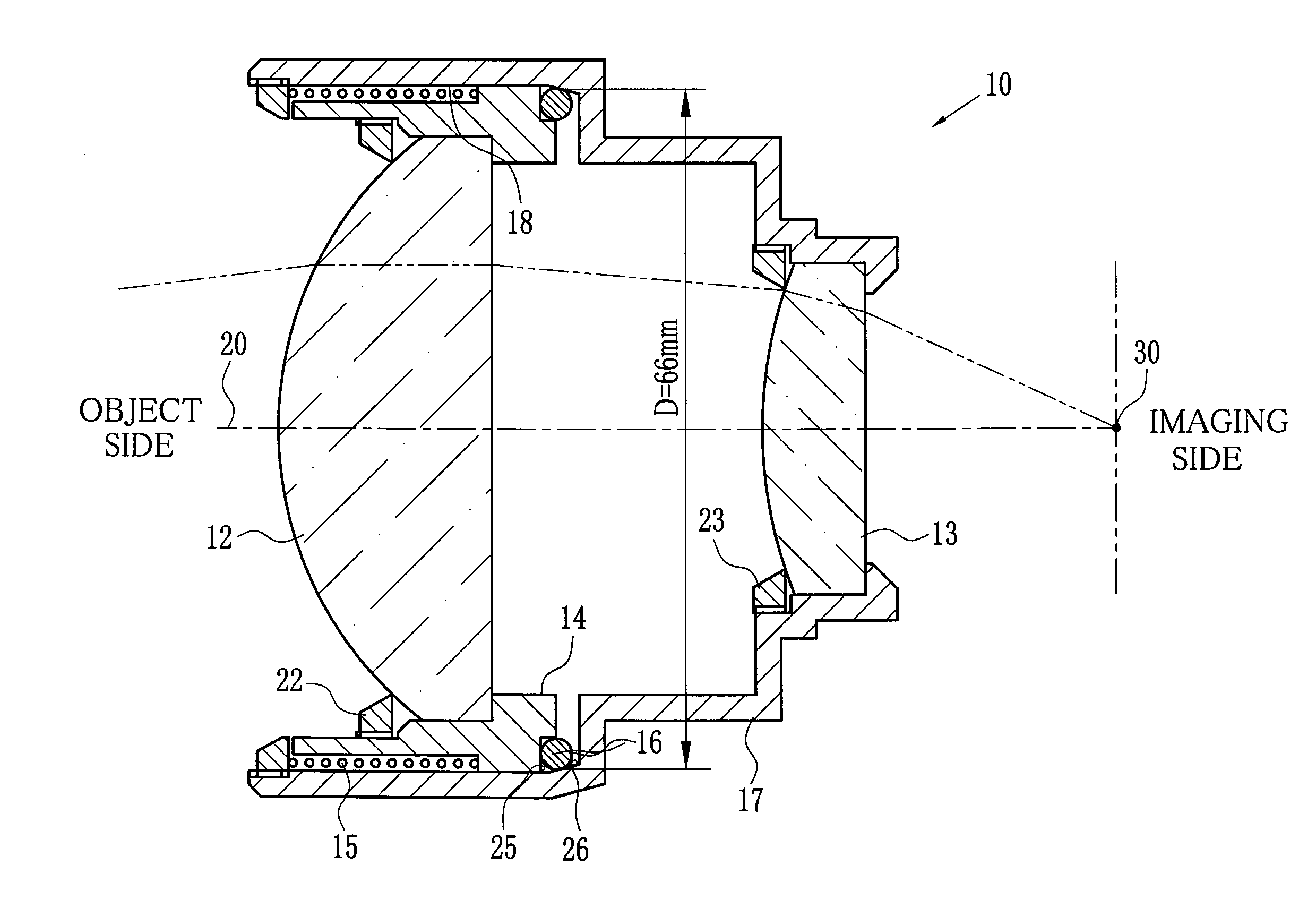
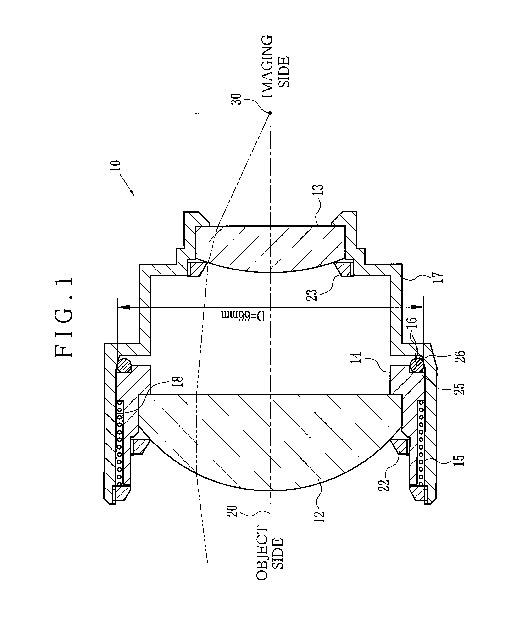
[0021]Shown in FIG. 1, an athermal lens device 10 of the present invention is provided with an imaging optical system consisting of lens elements (hereinafter referred to as lenses) 12 and 13. The athermal lens device 10 is used for, for example, an infrared surveillance camera. chalcogenide infrared lenses are used for the lenses 12 and 13. The athermal lens device 10 includes lenses 12 and 13, a lens holding frame 14 for containing and holding the lens 12, a coil spring 15 for pressing a lens holding frame 14 toward an imaging surface direction, a ring 16 formed by looping a rod-shaped material whose cross-sectional surface is circular, and a lens barrel 17 for containing them. The lens 12 is fixed by a lens retaining ring 22 and the lens 13 is located at the imaging surface side to the lens 12 and fixed by a lens retaining ring 23. The lens barrel 17 includes a lens accommodation 18 formed with a cylindrical shape around an optical axis 20 and movably supports the lens holding fr...


PUM


Abstract

The athermal lens device includes lenses, a lens holding frame, a coil spring for pressing the lens holding frame toward an imaging surface direction, a ring formed by looping a round bar, and a lens barrel for containing them. The lens holding frame includes a pressing surface intersecting with an optical axis at the imaging surface side. The lens barrel has a sliding contact surface formed with a conical shape at an end of the imaging surface side of the lens container. The ring is made of an invar material whose thermal expansion coefficient is very small, and disposed between the sliding contact surface and the pressing surface formed with a plain shape. The ring is constantly pressed to the sliding contact surface by bias of the coil spring via the pressing surface. Position of the lens holding frame changes according to environmental temperature to correct focus point.

Description

FIELD OF THE INVENTION[0001]The present invention relates to an athermal lens device automatically correcting defocusing caused by environmental temperature change.BACKGROUND OF THE INVENTION[0002]A focus position in a lens system used for such as a camera shifts according to environmental temperature change. In particular, an infrared surveillance camera or a vehicle-mounted camera used outdoors at night has wide range in an environmental temperature, and image blur due to shift of focus position is large. The shift of focus position in the lens system according to temperature change is caused by that lens refractive power changes due to thermal expansion / contraction of lens elements, and that interval between each lens changes due to thermal expansion / contraction of a lens barrel that holds the lens system.[0003]An athermal lens device is known as a lens device provided with a structure for automatically correcting defocus caused by the thermal expansion / contraction. The athermal ...

Claims


Application Information

Patent Timeline
IPC IPC(8): G02B7/02
CPCG02B13/14G02B7/028
Inventor KOJIMA, SHIGERU
Owner FUJIFILM CORP
Why Eureka
Try Eureka