

Vehicle light and multi-focal lens
- Summary
- Abstract
- Description
- Claims
- Application Information
AI Technical Summary
Benefits of technology
Problems solved by technology
Method used
Image

Examples
Embodiment Construction
[0035]A description will now be made below to vehicle lights and multi-focal lenses of the presently disclosed subject matter with reference to the accompanying drawings and in accordance with exemplary embodiments. Although various types of technical features are described with respect to the following exemplary embodiments described below in order to embody the presently disclosed subject matter, the scope of the presently disclosed subject matter is not limited to the following embodiments and illustrated examples.
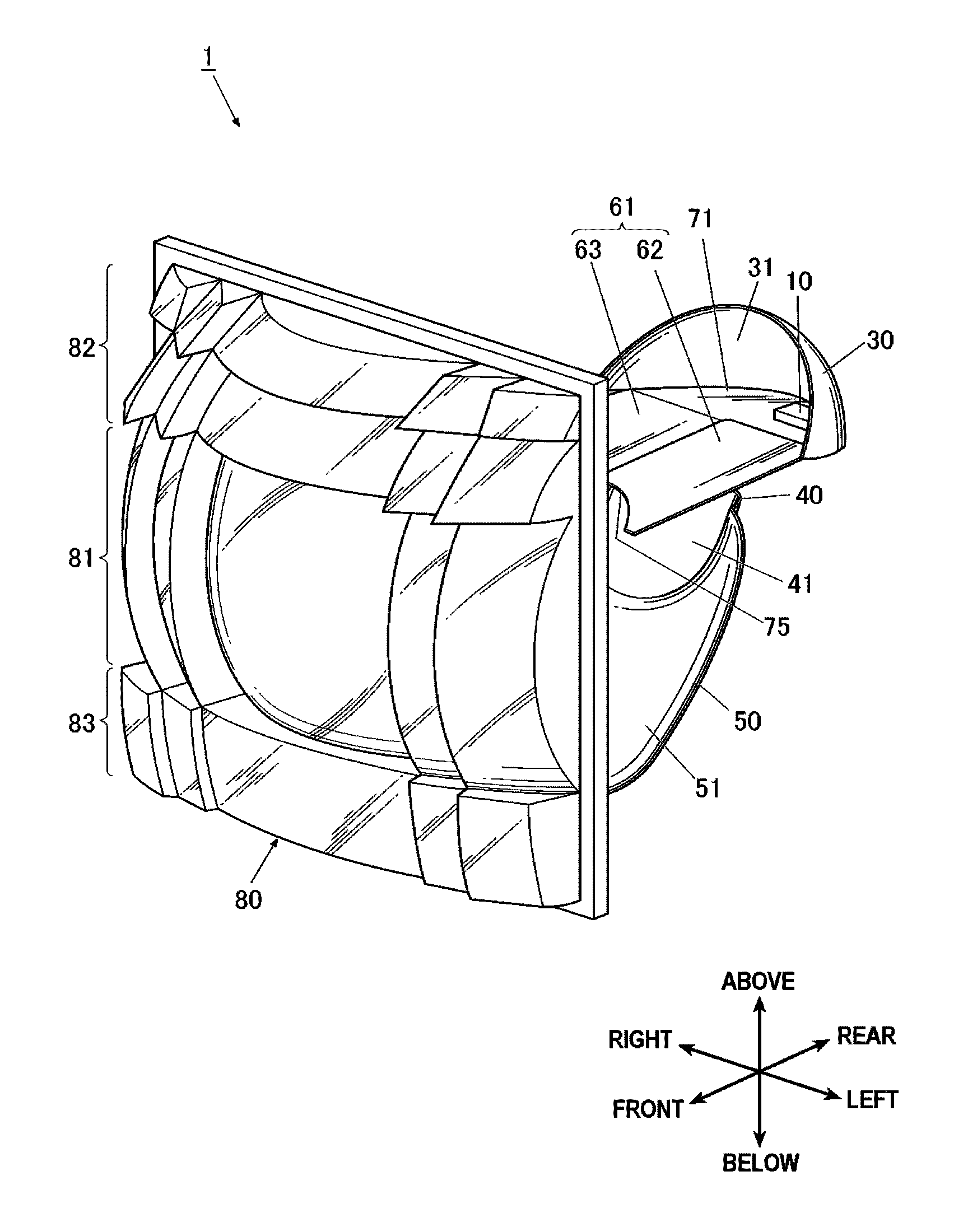
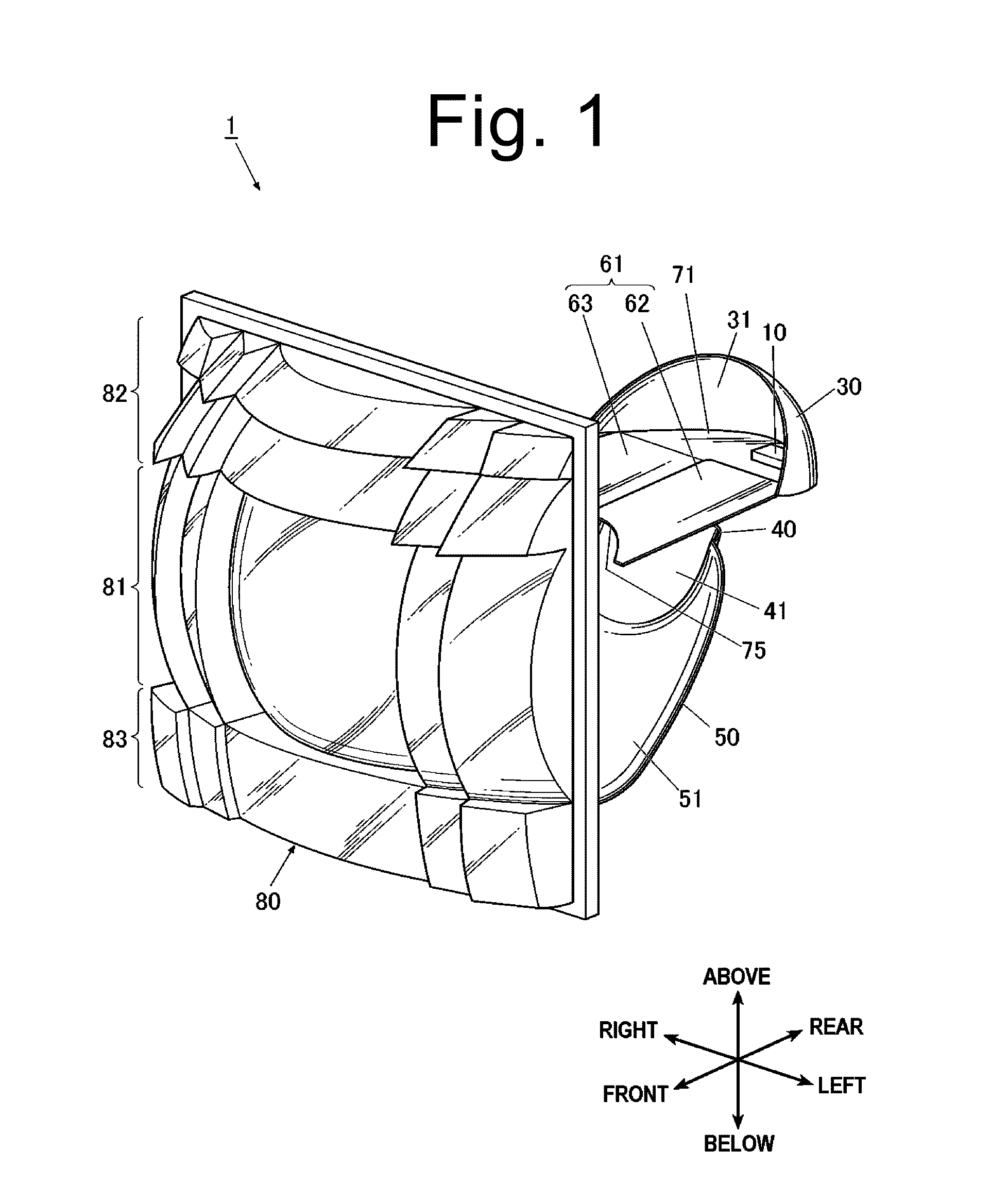
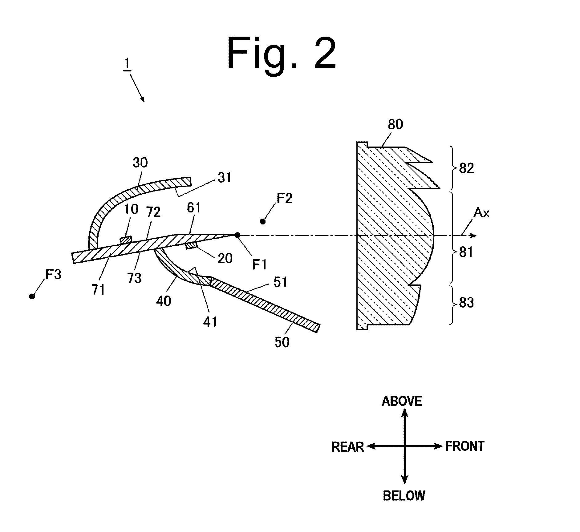
[0036]In addition, in the following description “above,”“below,”“front,”“rear,”“left,” and “right” refer to the “above,”“below,”“front,”“rear,”“left,” and “right,” respectively, of a vehicle equipped with a headlight. Furthermore, the direction along the longitudinal length of a vehicle body shall refer to “front-to-rear direction (equivalently rear-to-front direction)” or “longitudinal direction,” while the direction in the vehicle width direction shall refer to “horiz...
PUM
 Abstract
Description
Claims
Application Information