

Optical fiber ribbon holding member, optical fiber ribbon holding method, optical fiber ribbon bundle and holding member fixture
a technology of optical fiber ribbon and holding member, which is applied in the direction of optics, optical light guides, instruments, etc., can solve the problems of misalignment of the optical connector at the tip of the misaligned optical fiber ribbon with the position, inability to accurately position and arrange, and user's inability to move and readjust the position of each of the optical fiber ribbons to the proper position. , to achieve the effect of convenient holding and heating operation
- Summary
- Abstract
- Description
- Claims
- Application Information
AI Technical Summary
Benefits of technology
Problems solved by technology
Method used
Image

Examples
first embodiment
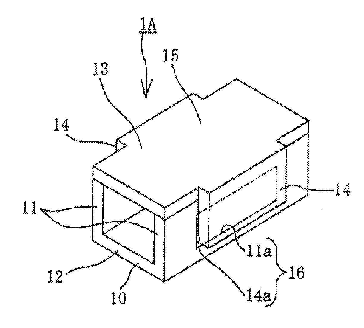
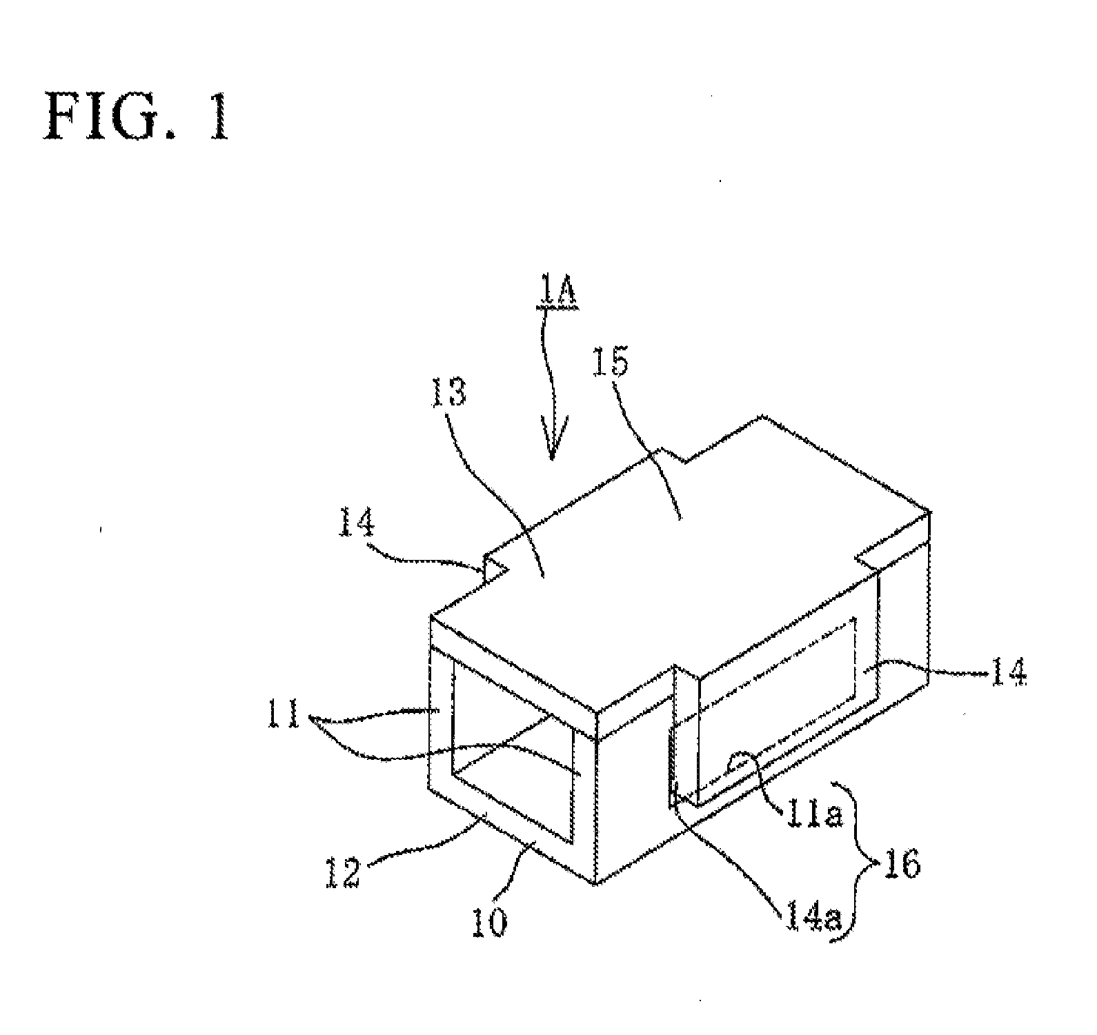
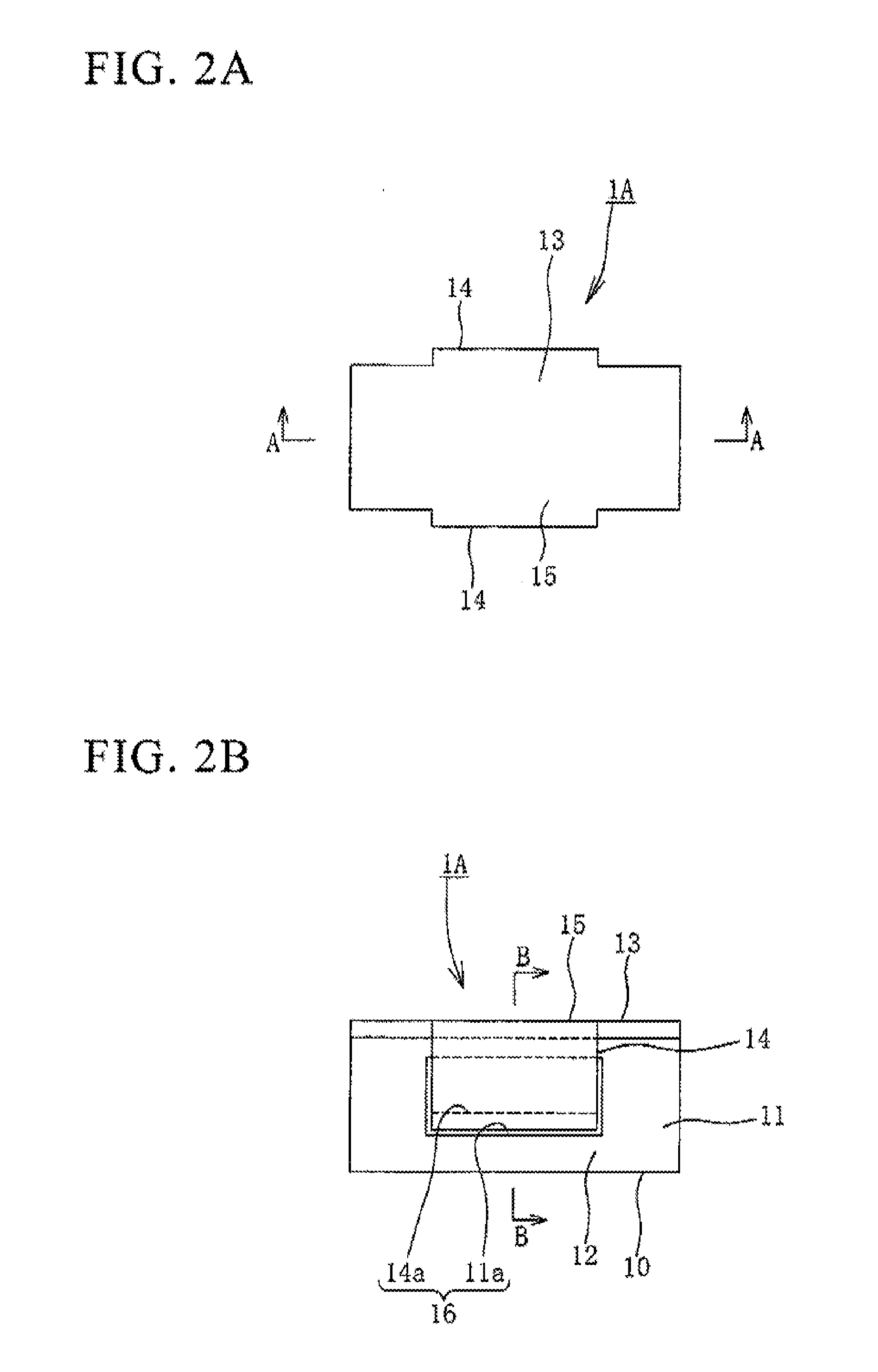
[0120]FIG. 1 is a perspective view illustrating an optical fiber ribbon holding member 1A of the first embodiment of the invention.
[0121]As shown in FIG. 7, an optical path change type optical connector 3, which is mounted on an photoelectric composite substrate 6 at a device bed plate 5 in a computer device and the like, is attached to a tip (first end portion) of each of optical fiber ribbons (optical fiber tape core wires) 2. The optical fiber ribbon holding member 1A holds a plurality of the optical fiber ribbons 2 in a laminated state and in a state in which the positions of the optical connectors 3 at the tips of the optical fiber ribbons 2 are misaligned with each other in a length direction of the ribbon. The optical fiber ribbon holding member 1A is fixed in a holding member fixture 52 for fixing the holding member that is fixed in a peripheral portion of the device bedplate 5.
[0122]The optical connector 3 changes and performs optical coupling between the optical fibers tha...
second embodiment
[0155]FIG. 13A is a perspective view illustrating an optical fiber ribbon holding member 1B of a second embodiment of the invention. FIG. 13B is a perspective view illustrating a state in which a lid body 25 (described below) is removed.
[0156]As shown in FIG. 19, an optical path change type optical connector 3, that is mounted on a photoelectric composite substrate 6 at a device bedplate 5 in a computer device and the like, is attached to a tip (first end portion) of the optical fiber ribbon (optical fiber tape core wire) 2. The optical fiber ribbon holding member 1B holds a plurality of optical fiber ribbons 2 in a laminated state, and in a state in which the positions of the optical connectors 3 of the tips of the optical fiber ribbons 2 are misaligned with each other in a longitudinal direction of the ribbon. In addition, the optical fiber ribbon holding member 1B is fixed in a holding member fixture 62 for fixing the holding member that is fixed in a peripheral portion of the de...
third embodiment
[0218]FIG. 32 is a side view of an optical fiber ribbon holding member 1G of a third embodiment of the invention. FIG. 33 is a plan view of the optical fiber ribbon holding member 1G. FIG. 34 is a right side view of the optical fiber ribbon holding member 1G.
[0219]As shown in FIG. 41, an optical path change type optical connector 3, that is mounted on an photoelectric composite substrate 6 at a device bedplate 5 in a computer device or the like, is attached to a tip (first end portion) of each of the optical fiber ribbons (optical fiber tape core wires) 2. The optical fiber ribbon holding member 1G holds four optical fiber ribbons 2 in a laminated state in the illustrated example, and in a state in which the positions of the optical connectors 3 of the tips of the optical fiber ribbons 2 are misaligned with each other in the longitudinal direction of the ribbon, and the optical fiber ribbon holding member 1G is fixed in a holding member fixture 72 for fixing the holding member that ...
PUM
| Property | Measurement | Unit |
|---|---|---|
| hardness | aaaaa | aaaaa |
| flexible | aaaaa | aaaaa |
| thickness | aaaaa | aaaaa |
Abstract
Description
Claims
Application Information