Golf club

a golf club and body technology, applied in the field of golf clubs, can solve the problems of little effort to structurally tune the golf club body to counteract the deleterious effect of mass manipulation, and achieve the effect of improving the structur

Active Publication Date: 2011-08-25
COBRA GOLF
View PDF15 Cites 68 Cited by
  • Summary
  • Abstract
  • Description
  • Claims
  • Application Information

AI Technical Summary

Benefits of technology

[0008]The present invention is directed to golf club heads having improved structure. In particular, a golf club head includes at least one truss member to tune the vibration characteristics during ball impact.
[0009]In an embodiment, a golf club head includes a perimeter body, a face, a hosel and at least one truss member. The perimeter body includes a top line and a sole portion. The face is disposed on a front portion of the perimeter body, and the face and the perimeter body define a rear cavity. The face and the sole portion are coupled at a periphery of the face to define a channel between the sole portion and the face. The hosel is disposed at a heel end of the face and the perimeter body. The at least one truss member extends across at least a portion of the rear cavity and mechanically couples the sole portion and an area of the top line exhibiting maximum displacement of a vibration mode in a frequency less than 5500 Hz.
[0010]In another embodiment, a golf club head includes a perimeter body, a face, a hosel and at least one truss member. The perimeter body includes a top line and a sole portion that forms a lower muscle portion. The lower muscle portion is at least partially hollow to define a lower cavity. The face is disposed on a front portion of the perimeter body, and the face and the perimeter body define an upper rear cavity in an upper portion of the golf club head. The hosel is disposed at a heel end of the face and the perimeter body. The at least one truss member extends across at least a portion of the upper rear cavity and mechanically couples the sole portion and an area of the top line exhibiting maximum displacement of a vibration mode in a frequency less than 5500 Hz.
[0011]In another embodiment, a golf club head includes a perimeter body, a face, a hosel and at least one truss member. The perimeter body includes a top line and a sole portion. The face is disposed on a front portion of the perimeter body, and the face and the perimeter body define a rear cavity. The hosel is disposed at a heel end of the face and the perimeter body. The at least one truss member extends across at least a portion of the rear cavity and mechanically couples an area of the sole portion and an area of the top line. The area of the top line exhibits maximum displacement of a vibration mode in a frequency less than 5500 Hz. The area of the sole portion exhibits maximum displacement of a vibration mode in a frequency less than 10,000 Hz.

Problems solved by technology

Unfortunately, those further manipulations have also altered the vibration and deflection characteristics of the golf club head which contribute to the feel, directional control and energy transfer to the golf ball during impact.
Little has been done to structurally tune the golf club body to counteract the deleterious effect of those mass manipulations.

Method used


Image

  • Golf club
  • Golf club
  • Golf club

Examples


Embodiment Construction

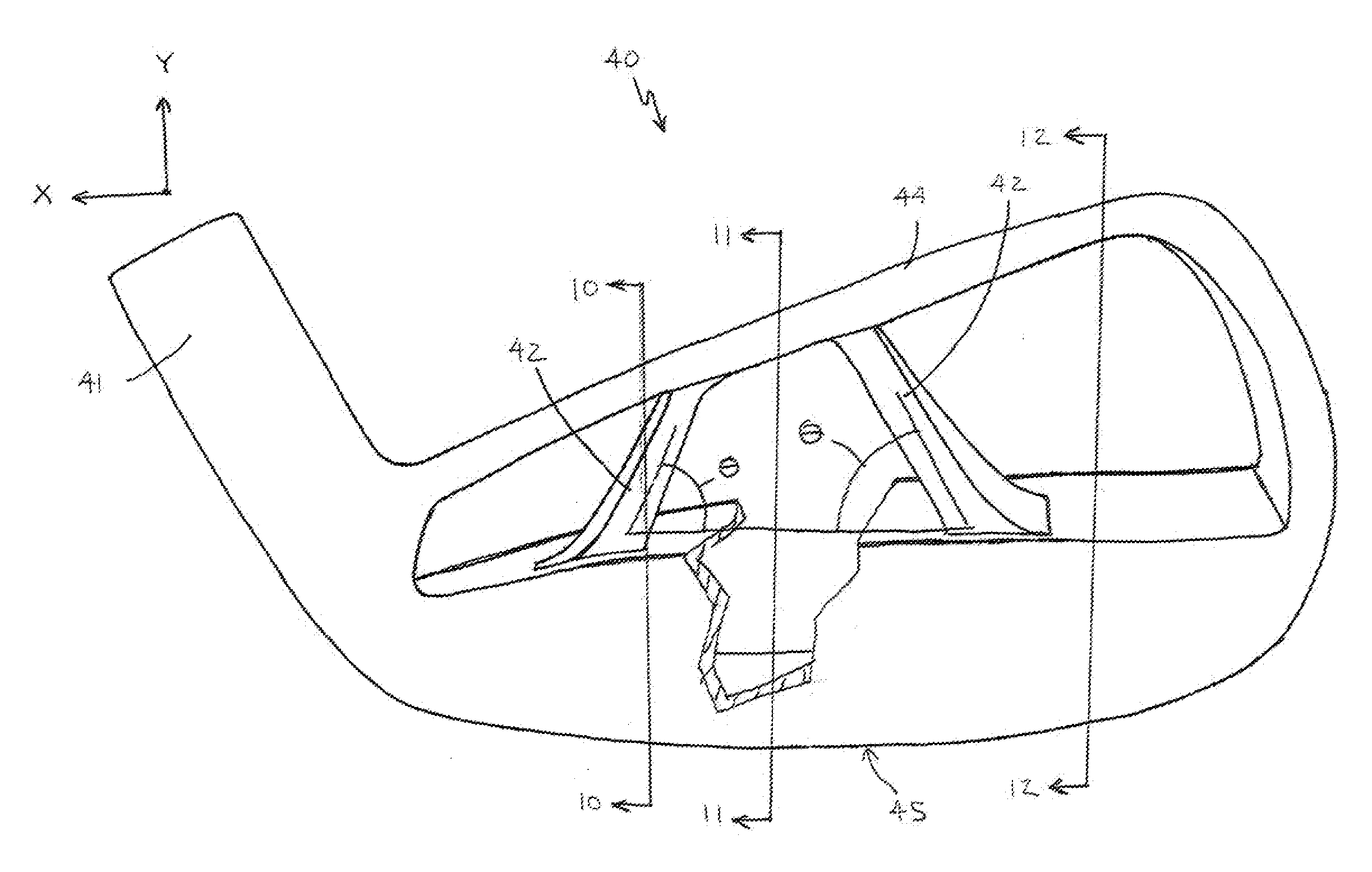
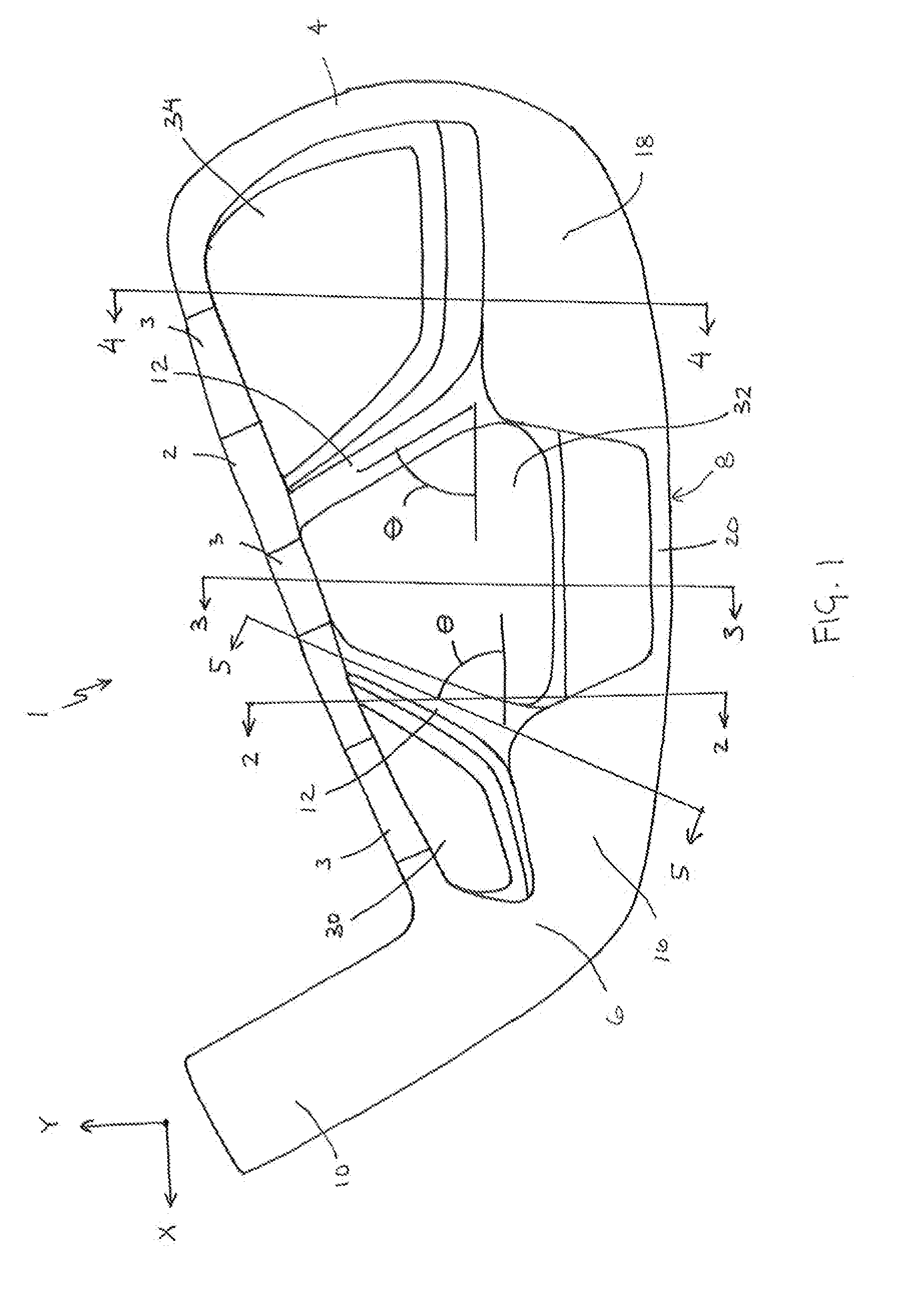
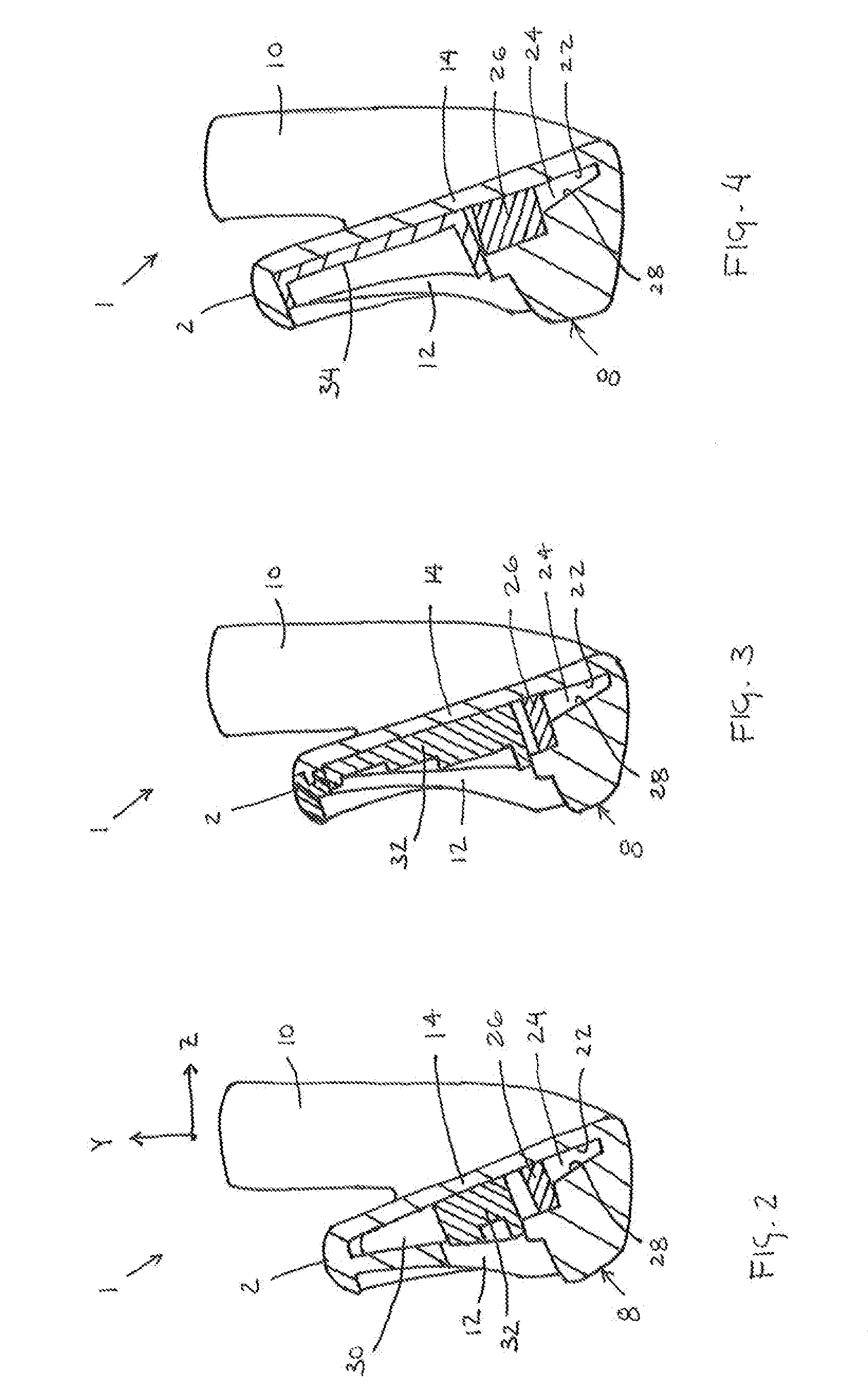
[0029]The present invention is directed to golf clubs having a truss structure in a rear portion of the golf club head. In particular, the truss structure is configured to alter the vibration characteristics of portions of the golf club head. The end result of the present invention is a club that provides improved sound, feel and distance control. Several embodiments of the present invention are described below.

[0030]Other than in the operating examples, or unless otherwise expressly specified, all of the numerical ranges, amounts, values and percentages such as those for amounts of materials, moments of inertias, center of gravity locations, loft and draft angles, and others in the following portion of the specification may be read as if prefaced by the word “about” even though the term “about” may not expressly appear with the value, amount, or range. Accordingly, unless indicated to the contrary, the numerical parameters set forth in the following specification and attached claim...


PUM


Abstract

A golf club includes a golf club head that is generally constructed as a perimeter weighted golf club head and comprises a perimeter body, a hosel, at least one truss member and a face. The truss member extends between portions of the perimeter body to tune the vibration and deflection response of the golf club head in response to a golf ball impact.

Description

FIELD OF THE INVENTION[0001]This invention generally relates to golf clubs, and more specifically to a golf club having a truss structure.BACKGROUND OF THE INVENTION[0002]Typical iron club heads are solid with a flat hitting face and generally have either a muscle back or a cavity back configuration. Traditionally, all irons had a muscle back configuration, which includes a thicker lower portion, a low offset hosel, a thin top line, a thin sole, and no substantial rear concavity.[0003]Irons with a cavity back configuration have material concentrated toward an outer periphery of the head to form a perimeter weight that defines a rear cavity. The cavity back configuration is used to provide mass distribution that makes the golf clubs more forgiving for less skilled users. For example, the cavity back configuration may be used to locate the center of gravity lower to the ground and rearward to launch a struck golf ball higher. The construction is also generally used to increase the rot...

Claims


Application Information

Patent Timeline
Patent Type & Authority Applications(United States)
IPC IPC(8): A63B53/04
CPCA63B53/047A63B53/0475A63B59/0092A63B2053/0441A63B2053/0491A63B2053/045A63B2053/0416A63B60/00A63B60/02A63B60/54A63B53/0416A63B53/0441A63B53/045A63B53/04A63B53/0433A63B60/002
Inventor BREIER, JOSHUA G.MORIN, JOHNROACH, RYAN L.
Owner COBRA GOLF
Why Eureka
Try Eureka