Failure Detection and Mitigation in Logic Circuits

a logic circuit and failsafe technology, applied in the direction of instruments, coding, code conversion, etc., can solve problems such as predetermined failsafe operation modes

Active Publication Date: 2011-08-25
WESTINGHOUSE ELECTRIC CORP
View PDF19 Cites 47 Cited by
  • Summary
  • Abstract
  • Description
  • Claims
  • Application Information

AI Technical Summary

Problems solved by technology

Any mismatch will result in a predetermined failsafe operational mode.

Method used


Image

  • Failure Detection and Mitigation in Logic Circuits
  • Failure Detection and Mitigation in Logic Circuits
  • Failure Detection and Mitigation in Logic Circuits

Examples


Embodiment Construction

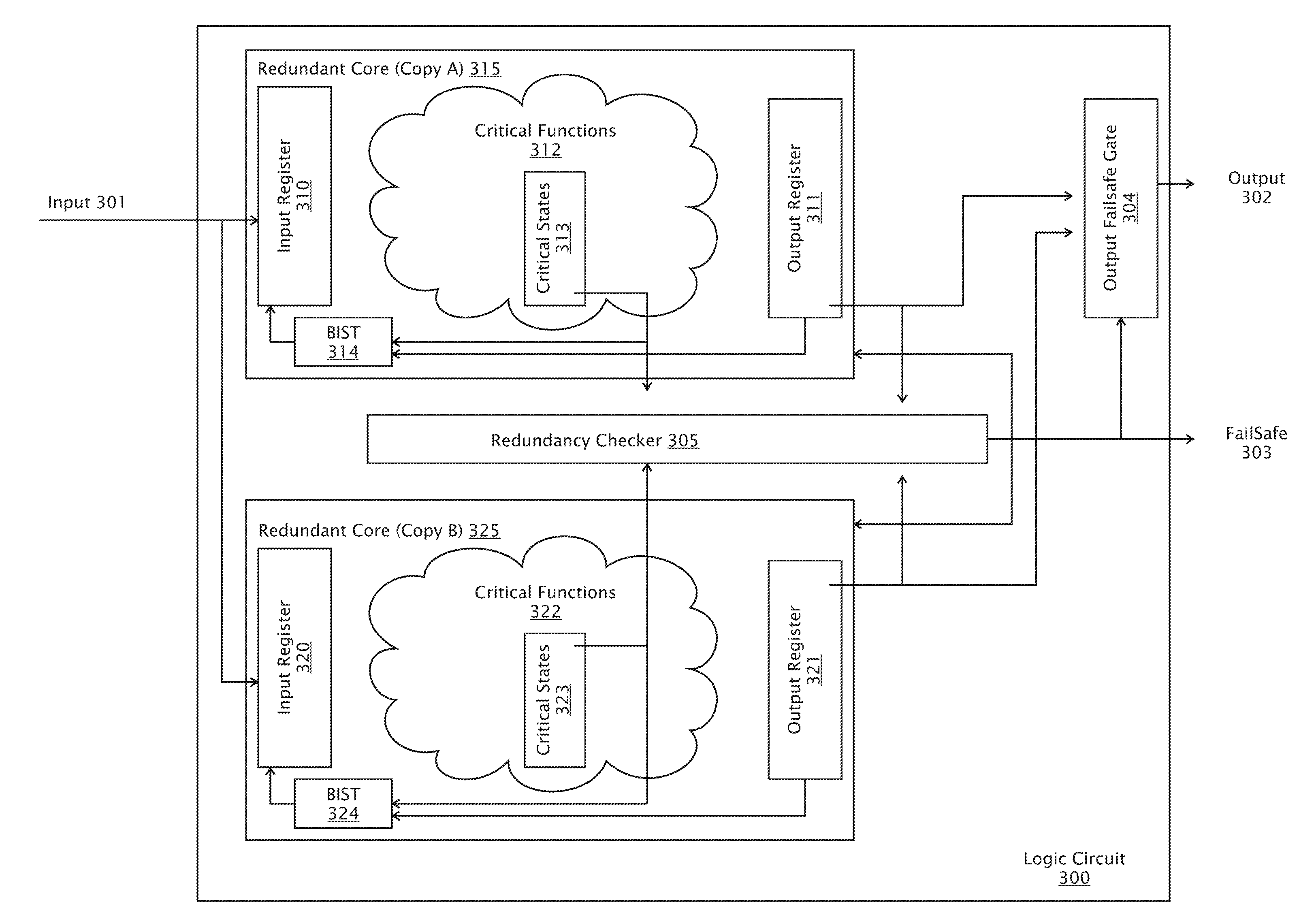
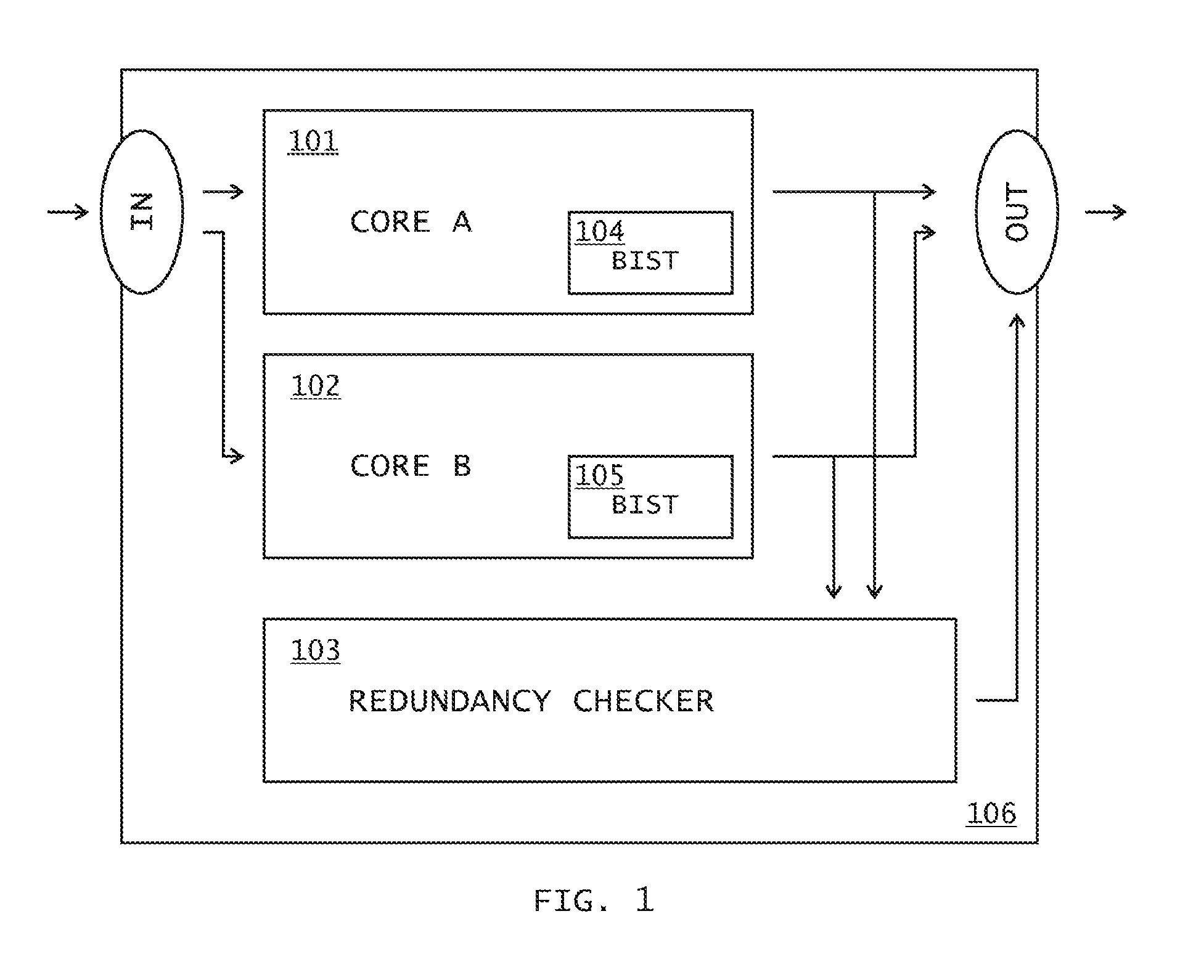
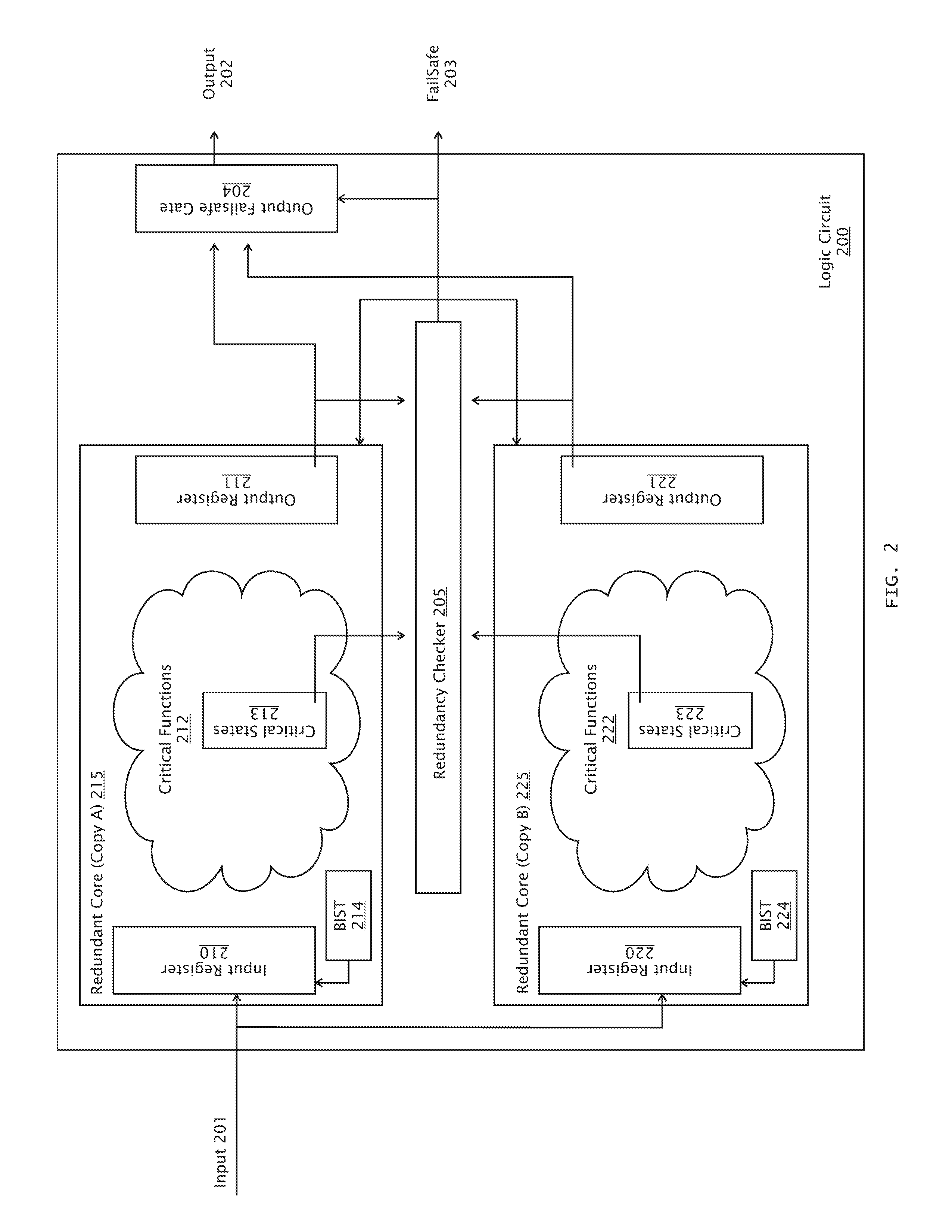
[0028]A primary object of the present invention is to provide for a highly reliable logic circuit, with assurance that it can perform the intended mission when called upon.

[0029]Another object of the present invention is to provide for a method for designing fail-safe logic circuits that are implemented in a single logic device such as PAL, CPLD, ASIC, Gate Array, or FPGA. Alternately and equally, the logic circuits are implemented in a combination of multiple logic devices on a single printed circuit board (PCB). Alternately and equally, they are implemented in a combination of multiple printed circuit boards with one or more logic devices such as PAL, CPLD, FPGA, ASIC, or Gate Array.

[0030]The invention may be combined with redundancy and / or fault tolerance at an application level by having multiple parallel systems capable of performing the mission. One method is to have two or more parallel systems capable of performing the missions. If one of these systems fails and enters a fai...


PUM


Abstract

The present invention is directed to methods of monitoring logic circuits for failures. In particular, the methods are directed toward establishing parallel logic cores where failures are detected by comparing the parallel paths for equivalence at key locations by a redundancy checker. Any mismatch will result in a predetermined failsafe operational mode. In addition, important techniques are applied to periodically exercise individual parallel paths to ensure that logic cores are verified in a way that does not disturb any process being monitored or controlled. This feature is important in some industries, such as the nuclear power industry, where safety critical operations require a high state of reliability on logic circuit blocks which may be infrequently utilized.

Description

CROSS REFERENCE TO RELATED APPLICATIONS[0001]This application is a continuation-in-part of U.S. patent application Ser. No. 12 / 026,703, filed on Feb. 6, 2008. The entire prior application is hereby incorporated herein by reference.STATEMENT REGARDING FEDERALLY SPONSORED RESEARCH OR DEVELOPMENT[0002]Not applicable.REFERENCE TO SEQUENCE LISTING, A TABLE, OR COMPUTER PROGRAM LISTING[0003]Not applicable.BACKGROUND OF THE INVENTION[0004](1) Field of the Invention[0005]The present invention generally pertains to a method for designing high integrity logic circuits. It is particularly directed toward safety-related control systems, including nuclear plant reactor protection systems, where integrity and reliability are of the highest importance. The present invention is especially directed toward implementing the methods in a logic device such as PAL, CPLD, FPGA, ASIC, or Gate Array, or in a combination of multiple logic devices. Such logic devices are commonly installed on printed circuit ...

Claims


Application Information

Patent Timeline
Patent Type & Authority Applications(United States)
IPC IPC(8): G01R31/3177G06F11/25
CPCA61B7/04A61B7/00
Inventor SORENSEN, STEEN DITLEVSOGAARD, STEN
Owner WESTINGHOUSE ELECTRIC CORP
Why Eureka
Try Eureka