
Architecture for high efficiency polymer photovoltaic cells using an optical spacer

a polymer and optical spacer technology, applied in the direction of semiconductor devices, solid-state devices, nanoinformatics, etc., can solve the problems of reducing the photovoltaic conversion efficiency, reducing the fill factor, and not meeting realistic commercialization specifications, so as to achieve the effect of redistributing the light intensity inside the devi

Inactive Publication Date: 2011-09-01
RGT UNIV OF CALIFORNIA
View PDF6 Cites 4 Cited by
  • Summary
  • Abstract
  • Description
  • Claims
  • Application Information

AI Technical Summary

Benefits of technology

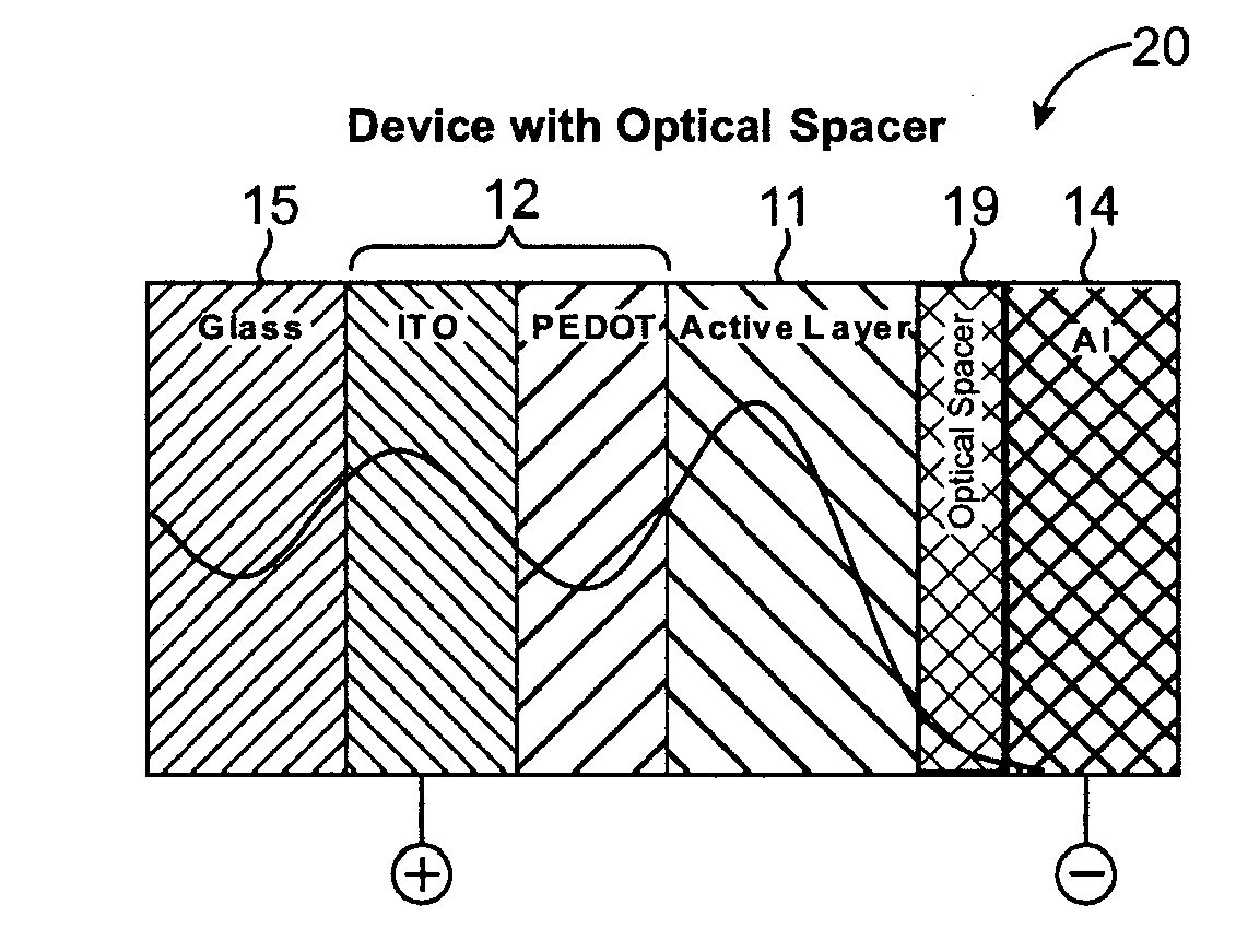
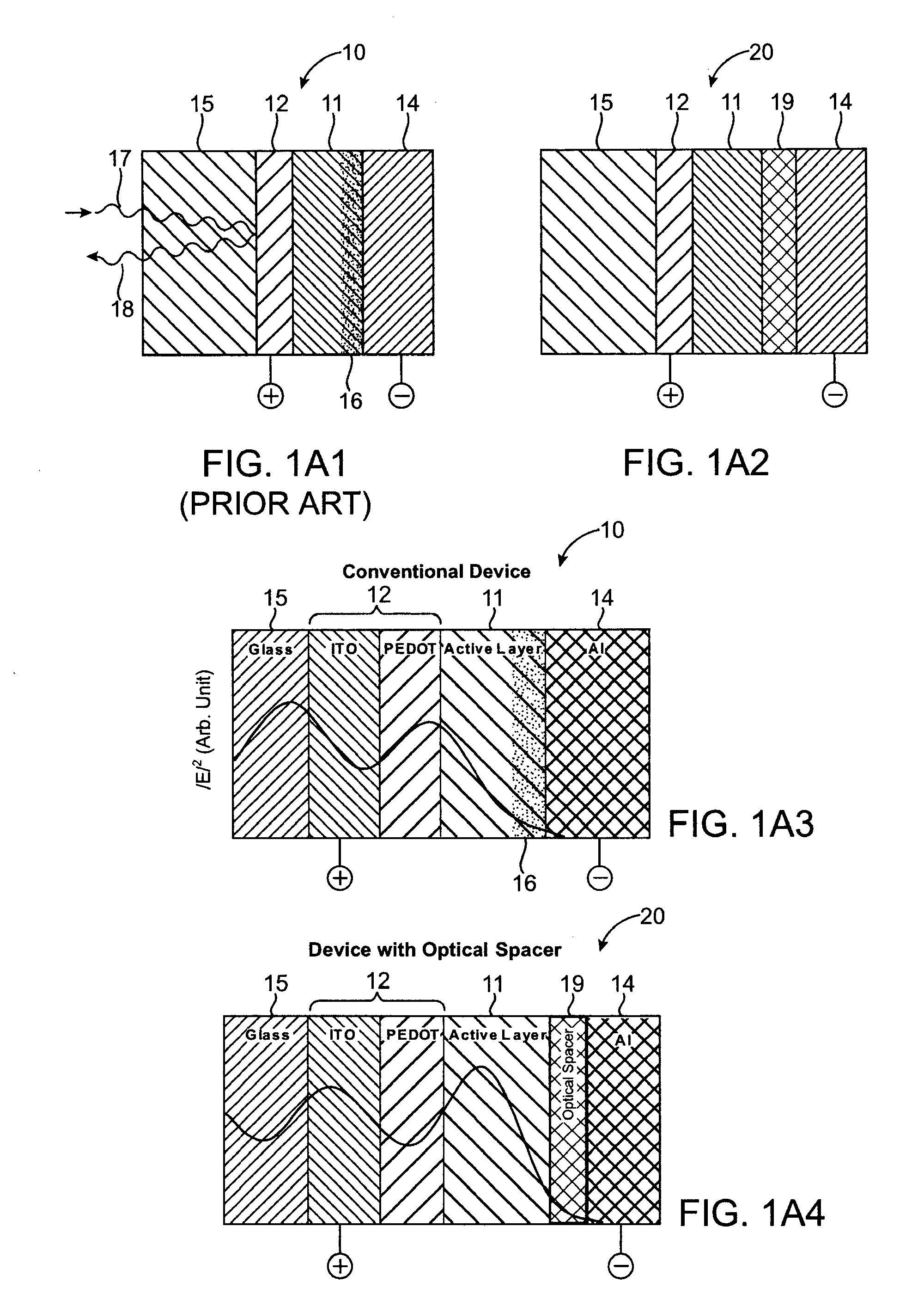
[0009]We have now found an alternative approach to solving this problem of internal reflection within polymer-based photovoltaic devices. This approach is to change the device architecture with the goal of spatially redistributing the light intensity inside the device by introducing an optical spacer 19 between the active layer 11 and the reflective electrode 14 as shown in device 20 sketched in FIGS. 1A2 and 1A4. Since spacer 19 is located within the light path and electrical circuit of device 20 it needs to be compatible with both the light and electrical flows. Thus, the prerequisites for an ideal optical spacer layer 19 include the following: First, the layer 19 should be constructed of a material which is a good acceptor and an electron transport material with a conduction band edge lower in energy than that of the highest occupied molecular orbital (HOMO) of the material making up the active layer; Second, the layer 19 should be constructed of a material having the energy of its conduction band edge above (or close to) the Fermi energy of the adjacent electron-collecting electrode; and Third, it should be transparent over a significant portion of the solar spectrum. In addition and preferably, the layer 19 should be of a thickness which, taking into consideration the material from which the layer is formed and that material's index of refraction, provides a redistribution of a significant portion of the internal reflection within the device. As shown in FIG. 1A4 this configuration can reduce or eliminate the dead zone 16 in active layer 11.
[0011]The spacer layer is substantially transparent in the visible wavelengths. It increases the efficiency of the device by modifying the spatial distribution of the light intensity within the photoactive layer, thereby creating more photogenerated charge carriers in the active layer.

Problems solved by technology

Although encouraging progress has been made in recent years with 3-4% power conversion efficiencies reported under AM1.5 (AM=air mass) illumination (5,6), this efficiency is not sufficient to meet realistic specifications for commercialization.
Moreover, this effect causes more electron-hole pairs to be produced near electrode 12, a distribution which is known to reduce the photovoltaic conversion efficiency (10,11).
Because of the low mobility of the charge carriers in the polymer-based active layers, however, the increased internal resistance of thicker films will inevitably lead to a reduced fill factor.

Method used


Image

  • Architecture for high efficiency polymer photovoltaic cells using an optical spacer
  • Architecture for high efficiency polymer photovoltaic cells using an optical spacer
  • Architecture for high efficiency polymer photovoltaic cells using an optical spacer

Examples


example 1

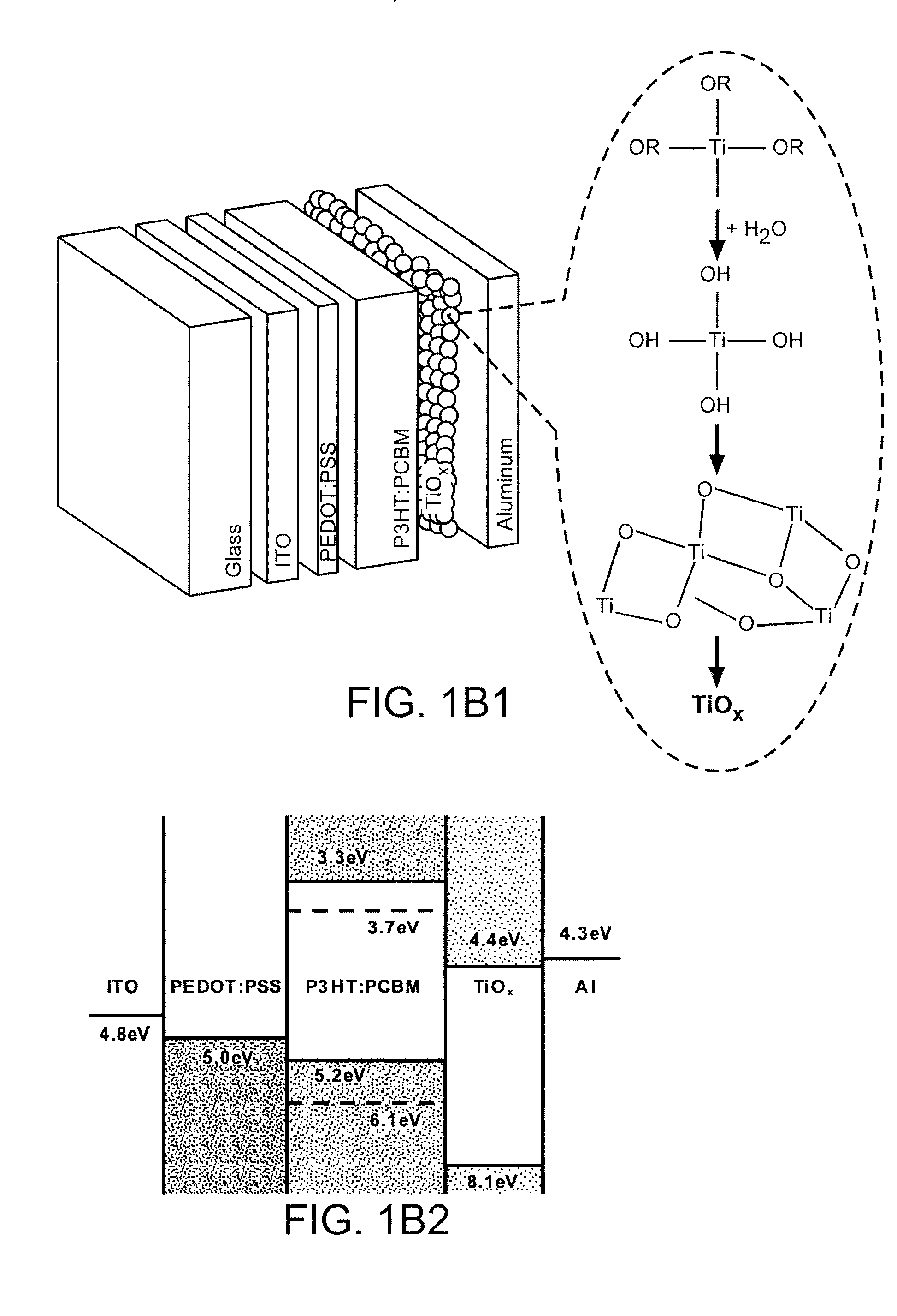
[0084]The sol-gel procedure for producing TiOx is as follows; titanium isopropoxide (Ti[OCH(CH3)2]4, Aldrich, 97%, 10 mL) was prepared as a precursor, and mixed with 2-methoxyethanol (CH3OCH2CH2OH, Aldrich, 99.9+%, 150 mL) and ethanolamine (H2NCH2CH2OH, Aldrich, 99.5+%, 5 mL) in a three-necked flask equipped with a condenser, thermometer, and argon gas inlet / outlet. Then, the mixed solution was heated to 80° C. for 2 hours in silicon oil bath under magnetic stiffing, followed by heating to 120° C. for 1 hour. The two-step heating (80° C. and 120° C.) was then repeated. The typical TiOx precursor solution was prepared in isopropyl alcohol.

[0085]For the preparation of the polymer-fullerene composite solar cells in the structure shown in FIGS. 1A4 and 1B1 and 1B2, we used regioregular poly(3-hexylthiopene) (P3HT) as the electron donor, and the fullerene derivative, [6,6]-phenyl-C61 butyric acid methyl ester (PCBM) as the electron acceptor. The P3HT:PCBM composite weight ratio was 1:1. ...


PUM

PropertyMeasurementUnit
thicknessaaaaaaaaaa
temperatureaaaaaaaaaa
transparentaaaaaaaaaa

Abstract

High efficiency polymer photovoltaic cells have been fabricated using an optical spacer between the active layer and the electron-collecting electrode. Such cells exhibit approximately 50% enhancement in power conversion efficiency. The spacer layer increases the efficiency by modifying the spatial distribution of the light intensity inside the device, thereby creating more photogenerated charge carriers in the bulk heterojunction layer.

Description

CROSS-REFERENCE TO RELATED PATENT APPLICATIONS[0001]This application is a continuation application of U.S. patent application Ser. No. 11 / 347,111, filed Feb. 2, 2006, which claimed the benefit under 35 USC 119(e) of U.S. Application Ser. No. 60 / 663,398, filed Mar. 17, 2005. U.S. patent application Ser. No. 11 / 347,111, filed Feb. 2, 2006 is also a continuation-in-part application of U.S. patent application Ser. No. 11 / 326,130, filed Jan. 4, 2006, which claimed the benefit under 35 USC 119(e) of U.S. Application Ser. No. 60 / 663,398, filed Mar. 17, 2005. All of the foregoing applications are hereby incorporated herein by reference in their entirety.BACKGROUND OF THE INVENTION[0002]1. Field of the Invention[0003]This invention relates to improved architecture for polymer-based photovoltaic cells and methods for the production of cells having the improved architecture.[0004]2. Background Information[0005]Photovoltaic cells having active layers based on organic polymers, in particular pol...

Claims


Application Information

Patent Timeline
Patent Type & Authority Applications(United States)
IPC IPC(8): H01L31/0232H01L51/46H01L31/18B82Y99/00
CPCB82Y10/00H01L51/0036H01L51/0037Y02E10/549H01L51/4226H01L51/4253H01L51/441H01L51/0047H10K85/1135H10K85/215H10K85/113H10K30/151H10K30/152H10K30/81H10K30/30H10K30/50H10K30/353
Inventor LEE, KWANGHEEHEEGER, ALAN J.
Owner RGT UNIV OF CALIFORNIA
Learn More