Step stool

a step stool and step technology, applied in the field of step stool, can solve the problems of inconvenient use and complicated steps, and achieve the effect of difficult us

Active Publication Date: 2011-09-01
NEW TEC INTEGRATION (XIAMEN) CO LTD
View PDF26 Cites 12 Cited by
  • Summary
  • Abstract
  • Description
  • Claims
  • Application Information

AI Technical Summary

Benefits of technology

[0020]The lock catch device, the connecting device and the footplate have been improved in a creative way, so that the step tool is used convenience with high reliability. With the hook groove of the lock catch hooking the rail in the present invention, the user can release the lock, turn the footplate and fold the step tool by catch the lock catch and lift it up. As the step tool is disposed with torsion spring, it can automatically lock up with high security. The lock catch device is disposed under the panel, so that it occupies little space, and retains the top footplate of holistic and handsome appearance. Both ends of the torsion spring withstand the plane and the panel separately; the lock catch gets clockwise torque, which ensures the substance of the lock catch and the high security. The handle is disposed with hand held groove, so that it is comfort for hand to release. A plastic element is disposed between the leg tubes and the footplate in the present invention, the first location slot fits the leg tubes and connects to the inner side of the leg tubes, the second location slot fits the leg tubes and connects to the end side of the footplate, which overcomes the said disadvantages of the existing step tool. The present invention has the advantages below:
[0021]1. preventing the footplate rotates relative to the lock pin and the leg tubes, which improves the security and the working life of the step tool;
[0023]3. enhancing the connecting strength between the footplate and the leg tubes;
[0024]4. Preventing the end surface of the footplate scratching the user. As the two lock pins are disposed with space between from up to down, it prevents the footplate rotates, with the high connecting strength between the leg tubes and the footplate. The footplate includes the supporting frame, which have the effects of connecting the component outsides, which is convenient for connecting. The lock pin is a rivet, which is convenient for assemble. The plastic element is cone shaped with the bigger end side touches the footplate and the smaller end side touches the leg tubes, which is convenient for the footplate rotation with reduced friction. At the same time, with the plastic element disposed between the leg tubes and the footplate, the footplate can be designed to new antiskid structure, which makes the step tool easily for use and high reliability.

Problems solved by technology

As we know from the above, the release steps includes several steps with complicated release and inconvenient usage.

Method used


Image

  • Step stool
  • Step stool
  • Step stool

Examples


second embodiment

The Second Embodiment

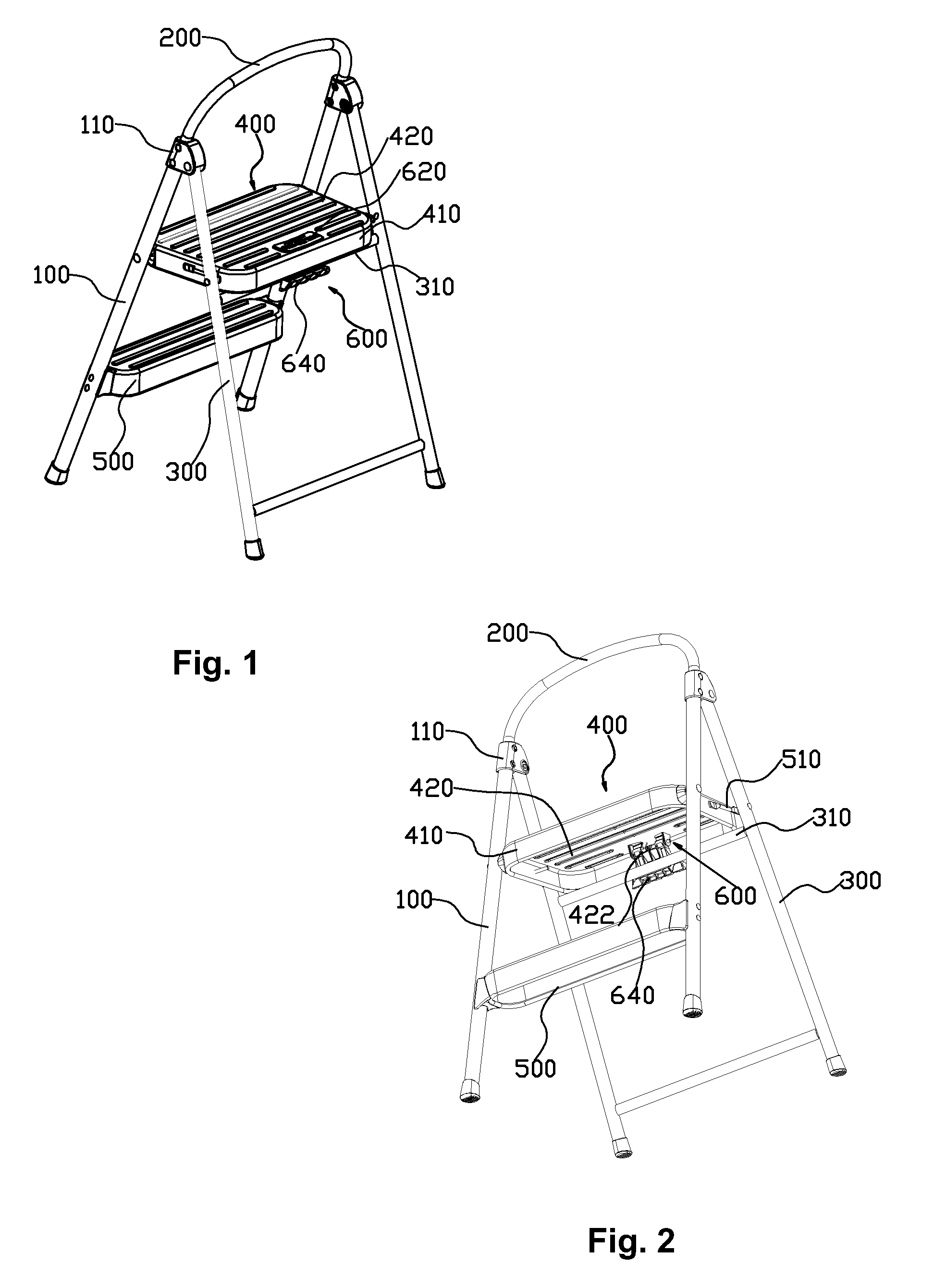
[0059]The step tool includes two front leg tubes 100, a U-shaped tube 200, two rear leg tubes 300, a top footplate 400, a bottom footplate 500 fixed between the two front leg tubes 100 and a lock catch device 600.

[0060]The end of the U-shaped tube 200 fixes to the top of the front leg tubes by a pivot 110, the top of the rear leg tubes 300 rotating joints to the pivot 110, so that the front leg tubes 100 rotation connects to the rear leg tubes. A rail 310 is disposed between the two rear leg tubes 300. (refer to the FIG. 1 and the FIG. 2)

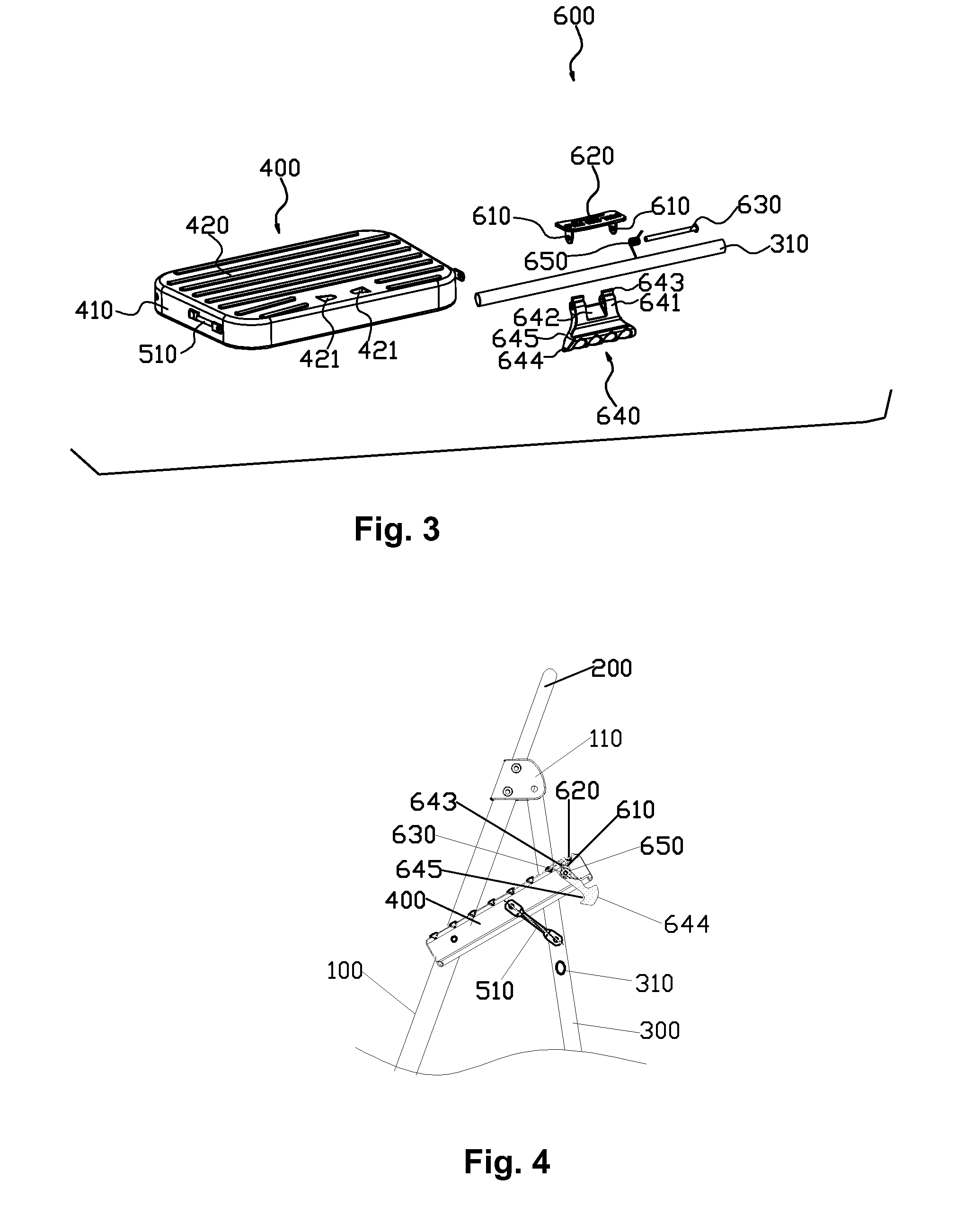
[0061]Refer to the FIG. 13, FIG. 14, FIG. 15 and FIG. 16, the top footplate 400 includes a substrate made from aluminum alloy and several antiskid strips 440 made from plastic.

[0062]The substrate is disposed with a rectangular figure supporting frame 410, a panel 420 and reinforcing ribs 430, the panel 420 is fixed on the supporting frame 410 and made in one step, the reinforcing ribs 430 joints the supporting frame 410 and supp...


PUM


Abstract

A step tool has front and rear leg tubes, a bottom and top footplate, a connection device for connecting the footplate and the leg tubes, a lock catch device of the top footplate. The front leg tubes are joined to the rear leg tubes rotatably. The foreside of the top footplate joins to the front leg tubes rotatably. A rail is fixed on the rear leg tubes. The lock catch is disposed on the top footplate and is detachedly connected to the rail. The lock catch device includes two connecting ears, a rotation axis, a lock catch and a torsion spring.

Description

FIELD OF THE INVENTION[0001]The invention relates to a step tool using on high.BACKGROUND OF THE INVENTION[0002]The existing step tool includes front leg tubes, the rear leg tubes, the top footplate and the lock catch device, the front leg tubes joint to the rear leg tube rotatably, the top footplate joint to the front leg tubes rotatably, a rail is disposed on the leg tubes. The lock catch device is disposed in the top footplate and joints to the rail, the leg tubes and a footplate disposed between the two leg tubes assembly and disassembly. As a special step tool for user to work on high, it requires high fixation effect of the top footplate of the step tool. The name of the letter patent is “a lock catch structure of the step tool” published in the Chinese patent data in Apr. 18, 2007. The notification number is CN2889017Y. A lock catch structure of the step tool includes a hook pivot to a first hinge plate, the hook rotates around the pivot point, the hook is disposed with a cha...

Claims


Application Information

Patent Timeline
Patent Type & Authority Applications(United States)
IPC IPC(8): A47C12/00E06C7/50E06C5/36
CPCA47C12/00E06C1/393E06C1/387E06C1/20E06C7/083
Inventor LENG, LUHAO
Owner NEW TEC INTEGRATION (XIAMEN) CO LTD
Why Eureka
Try Eureka