Image pickup apparatus and rangefinder

a technology of image pickup and rangefinder, which is applied in the field of image pickup apparatus and rangefinder, can solve the problems of large measurement error, difficult long searching time to determine the corresponding viewing position to the target, etc., and achieves low cost, high accuracy, and efficient measurement

Active Publication Date: 2011-09-01
RICOH KK
View PDF13 Cites 75 Cited by
  • Summary
  • Abstract
  • Description
  • Claims
  • Application Information

AI Technical Summary

Benefits of technology

[0012]It is a general object of at least one embodiment of the present invention to provide an image pickup apparatus having a range-finding function (mechanism) capable of efficiently measuring a distance range from an ultra-short distance range in millim

Problems solved by technology

However, the parallax of the stereo camera (parallax between the two cameras) decreases with an increase in the distance from the observer to the target, which may result in a large measurement error.
However, a viewing position from one camera to the target may greatly depart from a viewing position from the other camera to the target based on the positions of the two cameras as illustrated in FIGS. 19A and 19B, and hence searching time to determine the corresponding viewing positions to the target may take a long time.
In addition, different aspects of the target are to be viewed from the corresponding camera positions, and hence it may be difficult to determine the corresponding viewing positions to the target.
The related art multi-camera system utilizing the combination of the long baseline length stereo camera and the short baseline length stereo camera is capable of measuring a short distance range of 5 to 30 m and a long distance range of 20 to 100 m, which indicates the incapability of measuring a distance range between an ultra-short dista

Method used


Image

  • Image pickup apparatus and rangefinder
  • Image pickup apparatus and rangefinder
  • Image pickup apparatus and rangefinder

Examples


embodiments

[0038]The features of the embodiments are described below, with reference to the accompanying drawings.

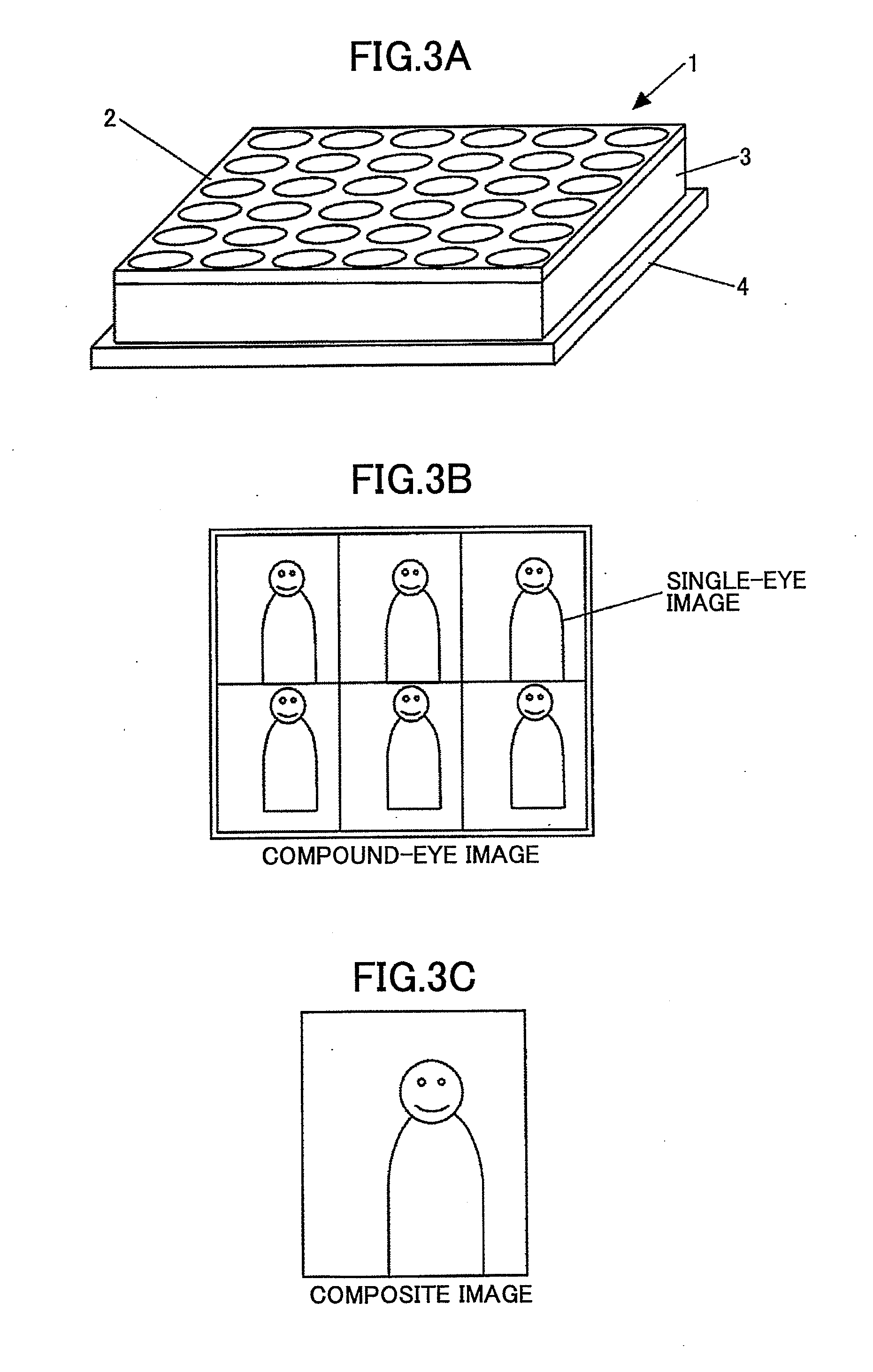
[0039]FIG. 3A is a diagram illustrating a configuration of a compound-eye camera including a lens array. As illustrated in FIG. 3A, a compound-eye camera 1 is configured to include a lens array 2 having plural lenses arranged in a plane, a sensor 3, and a substrate (printed circuit board) 4. The sensor 3 is configured to include an optical filter having plural regions in a lattice-like arrangement and an image pickup element such as a CCD or a CMOS. The plural images obtained via the plural lenses of the sensor 3 in FIG. 3A are integrated to form an image on the image pickup element. The number of lenses in the lens array 2 illustrated in FIG. 3A is only an example and may be including two or more lenses.

[0040]FIG. 3B illustrates an example of images obtained by the sensor 3 in a case where the number of lenses in the lens array 2 of the compound-eye camera 1 is 6. In FIG. 3B, plur...

first embodiment

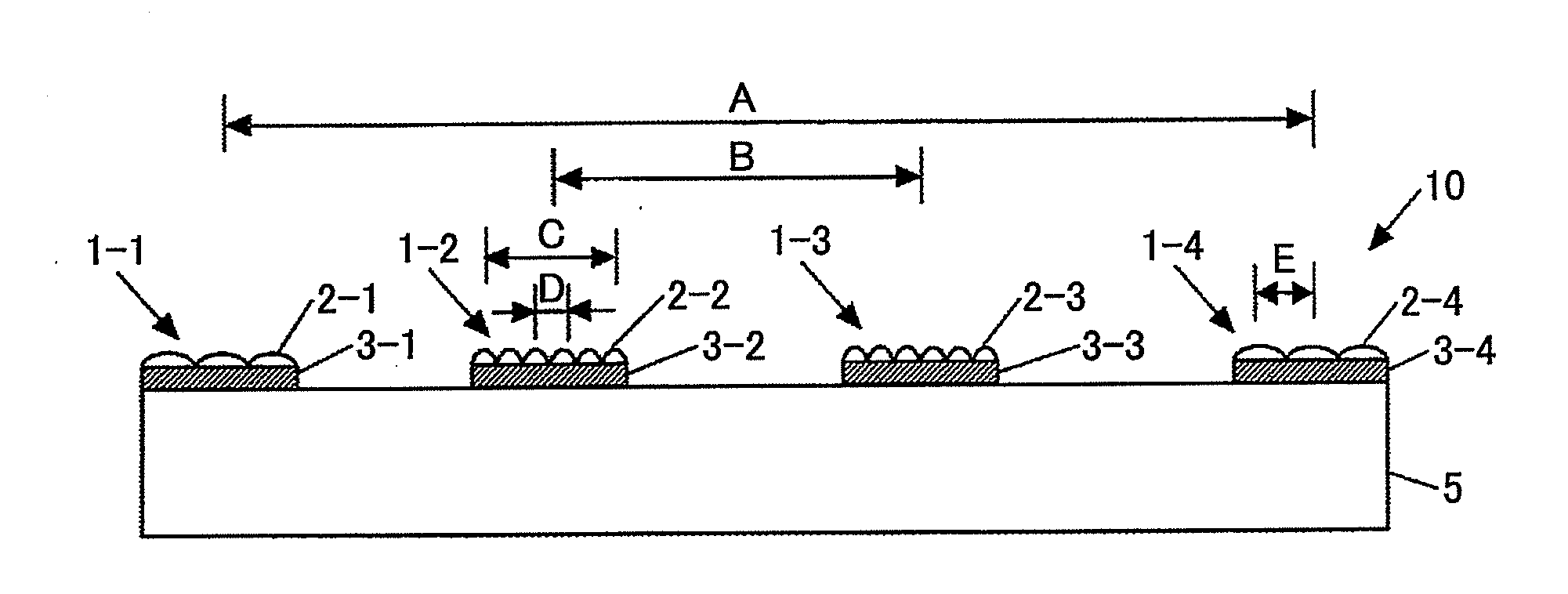
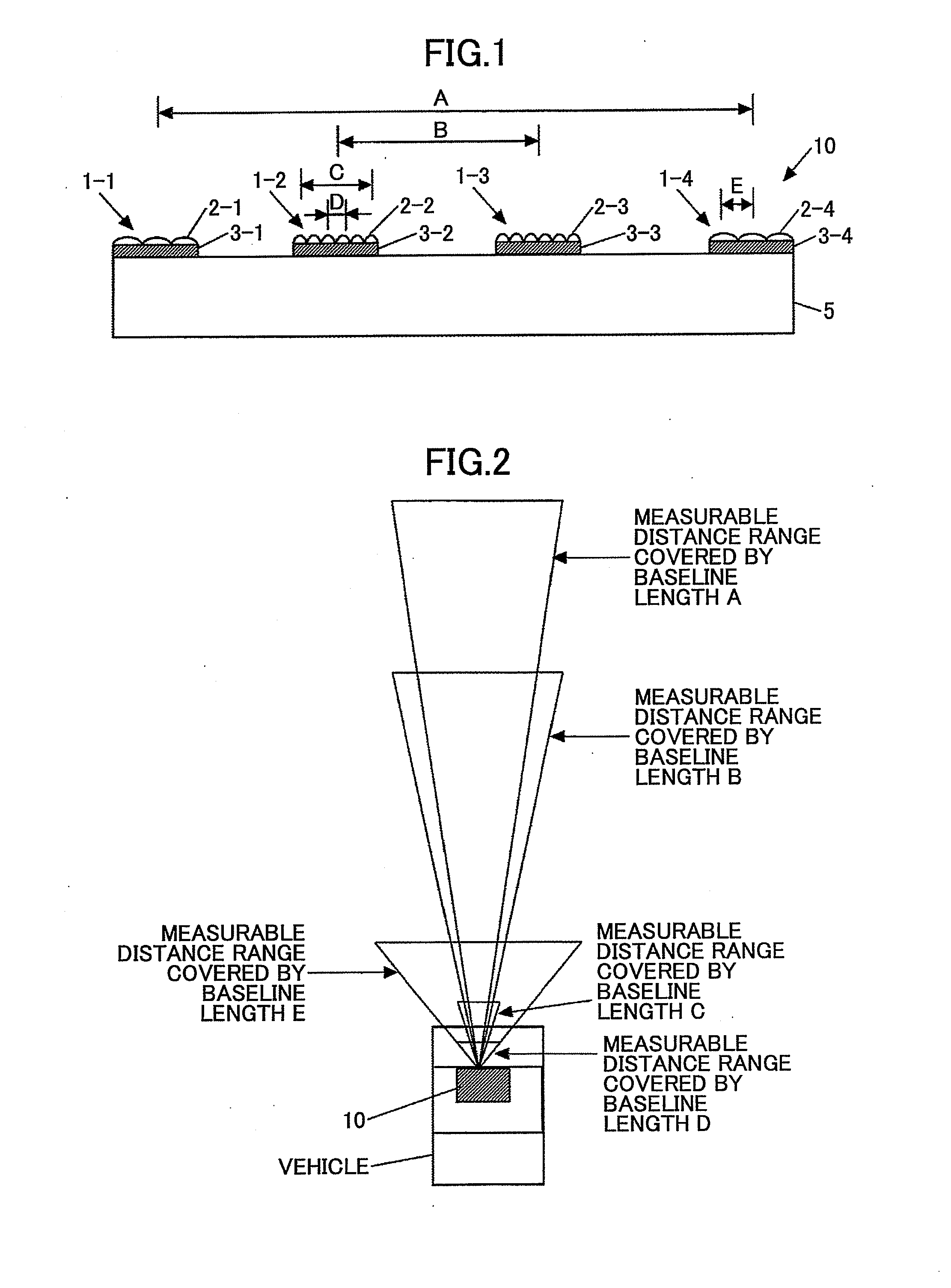
[0041]FIG. 1 is a diagram illustrating an image pickup apparatus (a compound-eye stereo camera) according to a first embodiment that utilizes plural compound-eye cameras having the configuration illustrated in FIG. 3A. The image pickup apparatus according to a first embodiment includes a set of two compound-eye cameras 1-1 and 1-4 having the same lens shape, and a set of two compound-eye cameras 1-2, and 1-3 having lens shapes differing from the lens shape of the compound-eye cameras 1-1 and 1-4. The two sets of the compound-eye cameras are arranged in a case (i.e., a camera unit) to form the image pickup apparatus (compound stereo eye camera). The compound-eye cameras 1-1, 1-2, 1-3, and 1-4 include respective lens arrays 2-1, 2-2, 2-3 and 2-4, and respective sensors 3-1, 3-2, 3-3 and 3-4 (substrate is not shown) in a manner similar to the compound-eye camera 1 illustrated in FIG. 3A.

[0042]Note that with only one compound-eye camera 1 illustrated in FIG. 3A, it is difficult to set t...

second embodiment

[0052]FIG. 5 is a diagram illustrating an example of an image pickup apparatus 11 according to a second embodiment that utilizes the compound-eye camera illustrated in FIG. 3A and two noncompound-eye cameras 6-1 and 6-2. In this case, since the cameras 6-1 and 6-2 having noncompound-eye lenses 7-1 and 7-2 do not use the composite image, the images captured by the sensors 8-1 and 8-2 have higher resolution. Thus, the number of sensors may be reduced compared to the number of sensors used in the image pickup apparatus 10 according to the first embodiment in FIG. 1. Compared to the configuration of FIG. 1, the configuration illustrated in FIG. 5 is capable of implementing accuracy in a longer distance measurement, and the accuracy in the ultra-short (near) distance measurement equal to or more than that obtained by the configuration of FIG. 1. However, the configuration illustrated in FIG. 5 may lower accuracy in an intermediate distance measurement covered by the baseline lengths B an...


PUM


Abstract

There is provided an image pickup apparatus for use in measuring a distance from an observer to a target. The image pickup apparatus includes a case; and a plurality of cameras configured to capture images of the target is fixed in the case. In the image pickup apparatus, the distance from the observer to the target is measured based on the images of the target captured by altering baseline lengths for parallax computation obtained by combining any two of the cameras.

Description

BACKGROUND OF THE INVENTION[0001]1. Field of the Invention[0002]The invention relates to an image pickup apparatus having two or more cameras capable of measuring a distance from an observer to a target and a rangefinder having such an image pickup apparatus.[0003]2. Description of the Related Art[0004]A rangefinder using a stereo camera is configured to take images of a same target from different visual points to measure a position of the target and a distance from an observer to the target based on a change in a distance between image forming points of the target in respective sensors. Recently, there is a growing concern in a driver's awareness of pedestrians in road safety' and a driver's support system to attach a stereo camera on a vehicle to provide the driver information on existence of pedestrians in the vicinity of the driver's vehicle, and the like is about to be put in practice.[0005]FIG. 18 illustrates a principle of a stereo camera system. The stereo camera system uses...

Claims


Application Information

Patent Timeline
IPC IPC(8): H04N7/18
CPCH04N7/181
Inventor YOKOTA, SOICHIRO
Owner RICOH KK
Why Eureka
Try Eureka