Wavelength Conversion

a wavelength conversion and optical technology, applied in the field of optical components, can solve the problems of low power density, limited luminance, and difficulty in cooling high-power leds in small packages, and achieve the effects of reducing the cost of optical components, and improving the efficiency of optical components

Active Publication Date: 2011-09-01
TEXAS INSTR INC
View PDF7 Cites 51 Cited by
  • Summary
  • Abstract
  • Description
  • Claims
  • Application Information

AI Technical Summary

Problems solved by technology

Solid state illuminators, however, have drawbacks.
The luminance, available flux within the etendue of a spatial light modulator (SLM), provided by an LED is limited, and high-power LEDs are difficult to cool in small packages.
Laser sources have a very high luminance, but tend to create image speckle artifacts due to their extremely narrow bandwidth.
Speckle artifacts are difficult and costly to eliminate in front projection display systems.

Method used


Image

  • Wavelength Conversion
  • Wavelength Conversion
  • Wavelength Conversion

Examples


Embodiment Construction

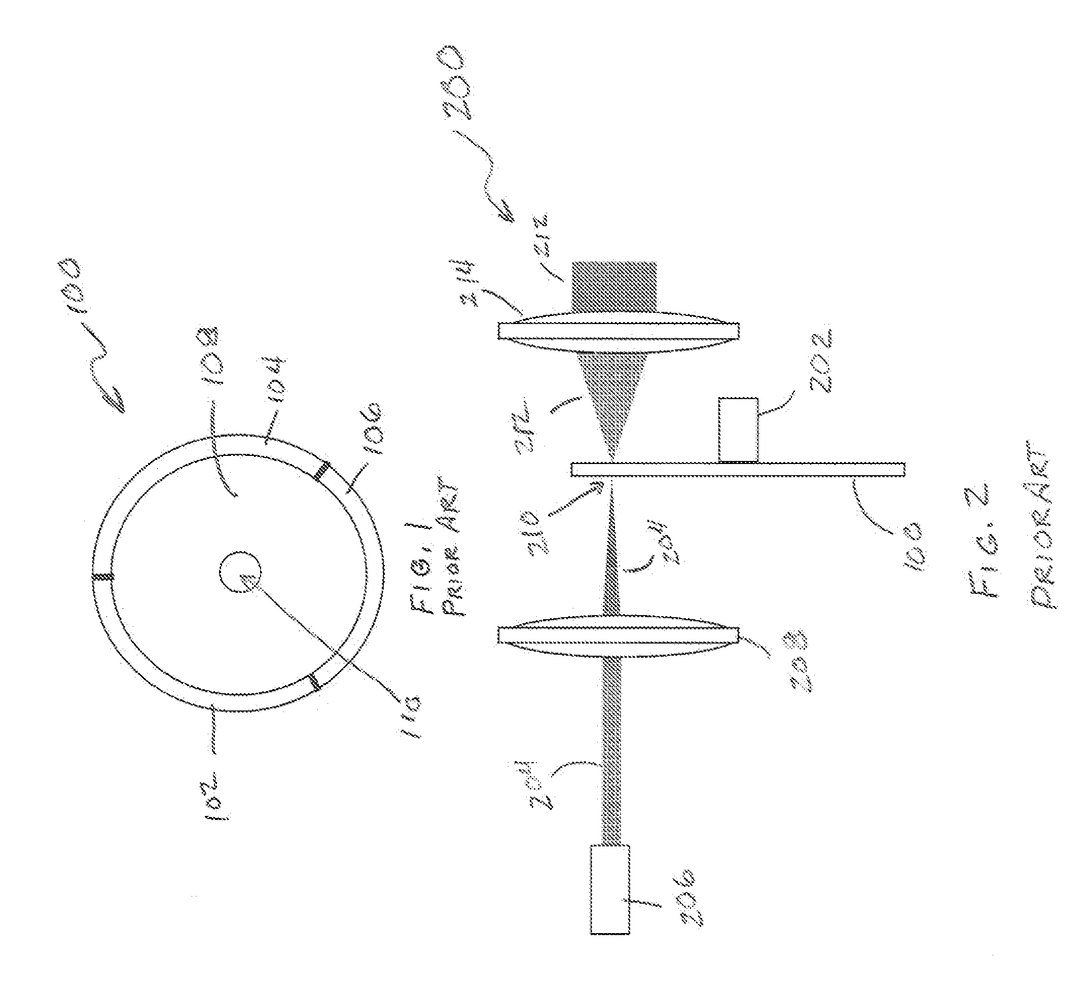
[0020]FIG. 1 is a plan view of a typical phosphor-based color wheel 100 of the prior art. The wheel, is comprised of multiple color segments 102, 104, 106, each of which is used to generate light having a particular color as will be explained later. The color segments 102, 104, 106 are attached to a central hub 108 which has a central aperture 110 through which a shaft is attached to the color wheel 100.

[0021]While three segments are shown in FIG. 1, the color wheel 100 of FIG. 1 may include more segments. For example, many color wheels include a single segment for each of three primary colors such as red, green, and blue. Other color wheels include multiple segments for a single color—either adjacent to segments of the same color or separated by segments of another color. Color wheels may also include additional colors such as cyan, magenta, and yellow, and may provide segments intended to generate white light—often called white or clear segments. While three primary colors have tr...


PUM


Abstract

A wavelength conversion device comprising a plurality of regions. Each region for absorbing radiant energy and emitting light having a characteristic dependent upon which region of the device emits the light.

Description

PRIORITY[0001]This applicant claims priority of provisional patent application No. 61 / 308,626 filed 26 Feb. 2010.FIELD OF THE INVENTION[0002]This invention relates to the field of optical components, more particularly to optical components that convert energy from one wavelength to another, more particularly optical components that convert energy from one wavelength to a visible wavelength, and display systems incorporating such wavelength conversion components.BACKGROUND OF THE INVENTION[0003]A variety of useful devices receive radiant energy in a first wavelength band and emit radiant energy in a different wavelength band. For example, periodically poled crystals, such as lithium niobate, are used to double the frequency of laser illumination and phosphors are deposited on the inside of cathode ray tubes to convert a stream of electrons into visible light.[0004]One such wavelength converter is a phosphor color wheel that receives radiant energy and emits visible light. The phospho...

Claims


Application Information

Patent Timeline
Patent Type & Authority Applications(United States)
IPC IPC(8): F21V9/16
CPCG03B21/204H04N9/3111F21V9/08
Inventor BARTLETT, TERRY ALAN
Owner TEXAS INSTR INC
Why Eureka
Try Eureka