
Method and system for operating a multi-user multiple-input multiple output (mu-mimo) wireless communications system

a wireless communication system and multi-user technology, applied in the field of wireless communications systems, can solve the problems of different intra-cell interference and consequently different cqis, operations consume valuable ue processing and uplink signaling resources, and ues do not necessarily know the usag

Active Publication Date: 2011-09-01
STMICROELECTRONICS INT NV
View PDF13 Cites 46 Cited by
  • Summary
  • Abstract
  • Description
  • Claims
  • Application Information

AI Technical Summary

Benefits of technology

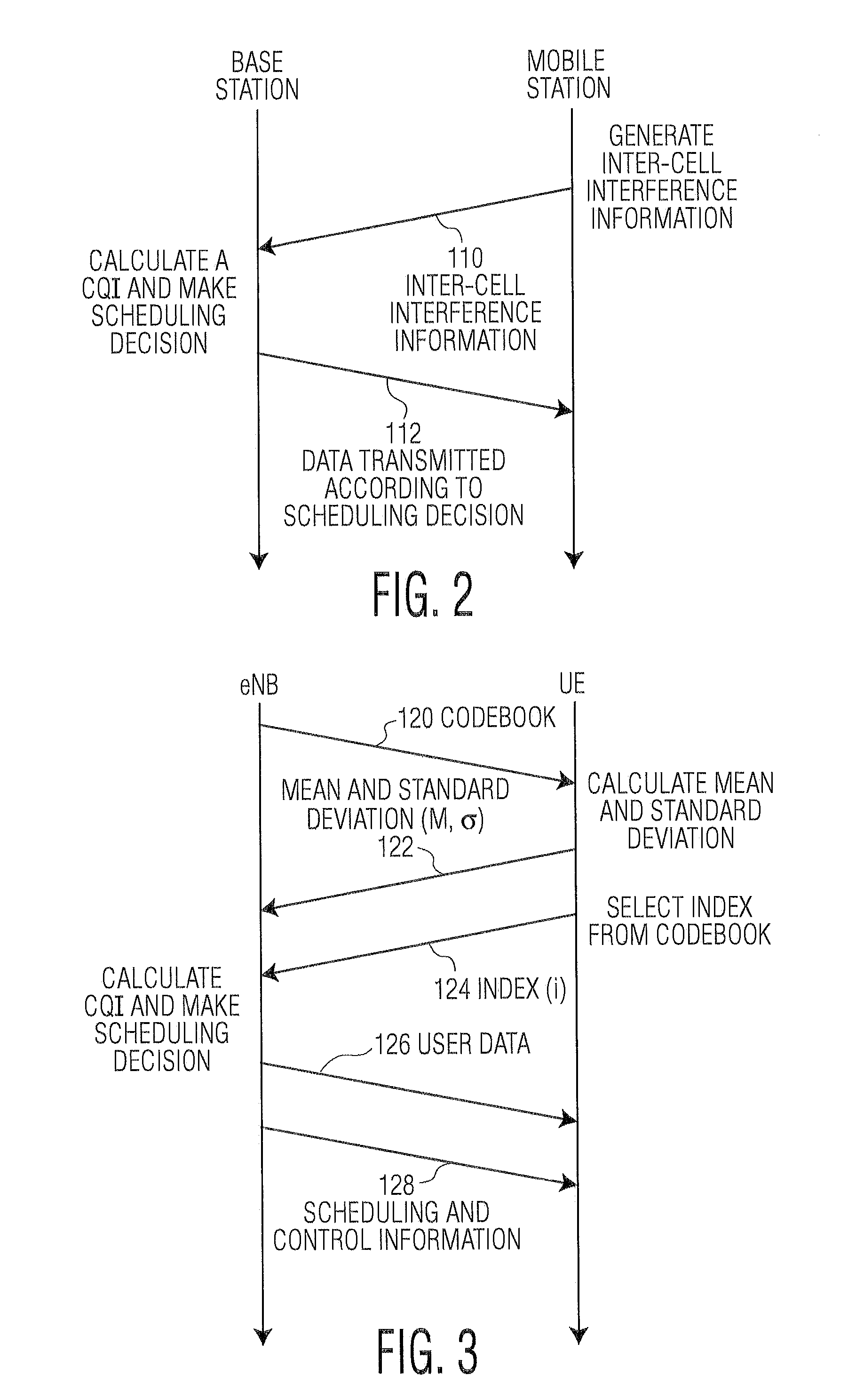
[0005]In an embodiment in accordance with the invention, instead of calculating a variety of CQIs at each UE, inter-cell interference information is generated at the UEs and transmitted to the eNB. At the eNB, CQIs are calculated for the UEs using the eNB's knowledge of the equivalent channel matrix and the usage scheme of each spatial sub-channel along with the inter-cell interference information that is transmitted from the UEs. Because the eNB has the inter-cell interference information from the UEs along with the equivalent channel matrix and the usage scheme of each spatial sub-channel, the calculated CQIs accurately reflect the conditions at the UEs. The calculated CQIs are then used to make scheduling decisions at the eNB and data is transmitted between the eNB and the UEs according to the scheduling decisions. Calculating the CQIs at the eNB instead of at the UEs avoids the need to have the UE calculate multiple different CQIs and avoids the need to burden the uplink channels with carrying those CQIs to the eNB.

Problems solved by technology

However, when operating in MU-MIMO mode, the UEs do not necessarily know the usage scheme (pre-coding) that will be used in the next transmission time interval (TTI) for each spatial sub-channel.
In MU-MIMO mode, different spatial sub-channel usage schemes will result in different intra-cell interference and consequently different CQIs.
A drawback to calculating multiple different CQIs at each UE and transmitting the multiple different CQIs to the eNB is that these operations consume valuable UE processing and uplink signaling resources.

Method used


Image

  • Method and system for operating a multi-user multiple-input multiple output (mu-mimo) wireless communications system
  • Method and system for operating a multi-user multiple-input multiple output (mu-mimo) wireless communications system
  • Method and system for operating a multi-user multiple-input multiple output (mu-mimo) wireless communications system

Examples


Embodiment Construction

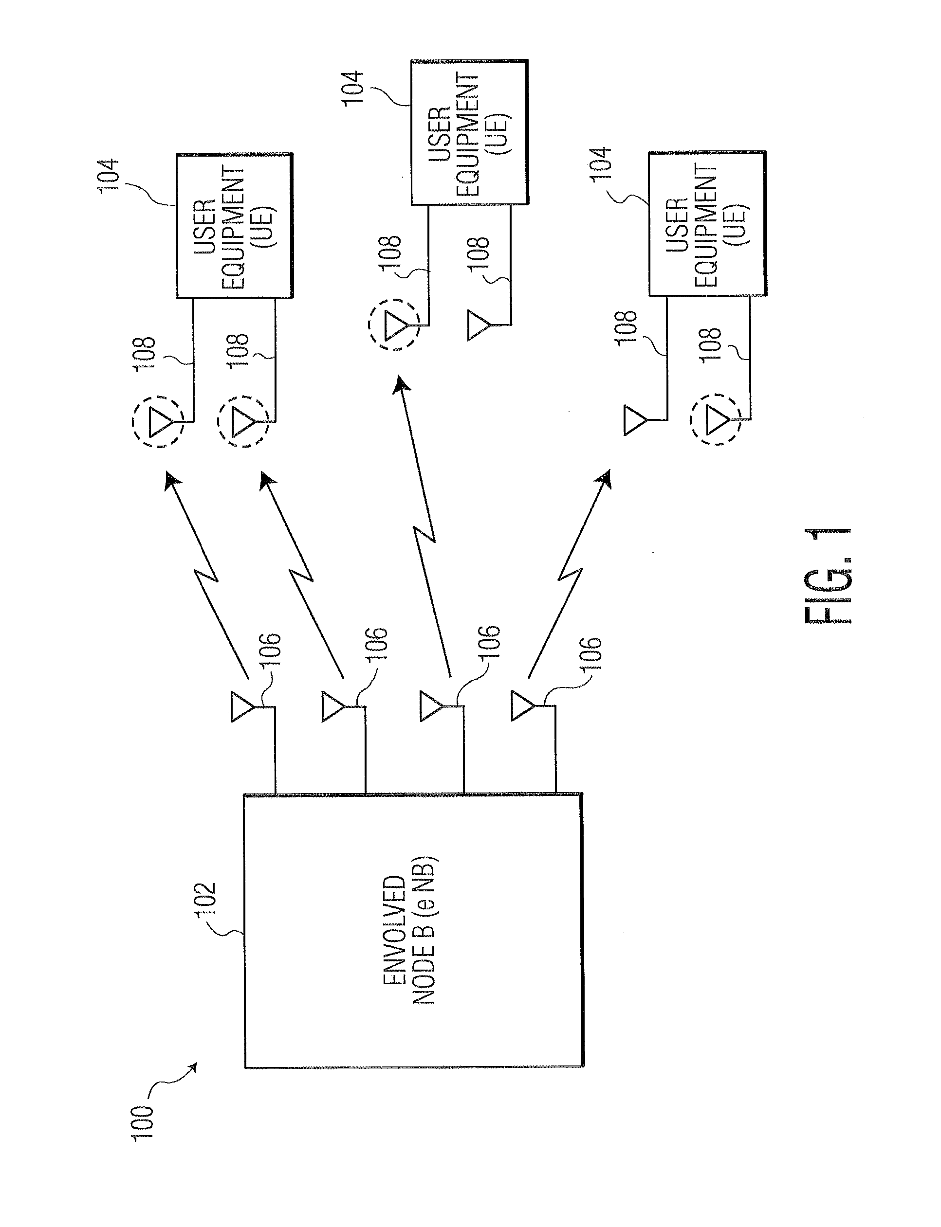
[0014]Multi-user multiple-input multiple-output (MU-MIMO) is an advanced spatial multiplexing technique for downlink transmission. FIG. 1 depicts a wireless communications system 100 that includes a base station 102 (referred to herein as an evolved Node B (eNB)) and multiple mobile stations 104 (referred to herein as user equipments (UEs)). The wireless communications system is operated in MU-MIMO mode using time division duplexing (TDD). In the embodiment of FIG. 1, the eNB is a wireless communications base station that supports MU-MIMO operation as specified in the 3GPP Long Term Evolution (LTE) specification. The eNB includes four antennas 106 although the eNB can include more than four antennas. In the embodiment of FIG. 1, the UEs are wireless communications mobile stations that support MU-MIMO operation as specified in the 3GPP LTE specification. Each of the UEs has two antennas 108, although the UEs are not limited to two antennas (e.g., the UEs can include only one antenna ...


PUM


Abstract

A technique for operating a wireless communications system that supports multi-user multiple-input multiple-output (MU-MIMO) communications between a base station and multiple mobile stations involves generating inter-cell interference information at the mobile stations and providing the inter-cell interference information to the base station. The base station uses the inter-cell interference information to calculate channel quality indicators (CQIs) and then makes scheduling decisions in response to the CQIs. Data is transmitted from the base station to the mobile stations according to the scheduling decisions.

Description

FIELD OF THE INVENTION[0001]The invention relates generally to wireless communications systems, and more particularly, to managing channel quality indicators in a multi-user multiple-input multiple-output wireless communications network.BACKGROUND OF THE INVENTION[0002]The 3rd Generation Partnership Project (3GPP) was established to produce globally applicable technical specifications and technical reports for a 3rd generation mobile system based on evolved Global System for Mobile communications (GSM) core networks and the radio access technologies that they support (i.e., Universal Terrestrial Radio Access (UTRA) in both Frequency Division Duplex (FDD) and Time Division Duplex (TDD) modes). The scope was subsequently amended to include the maintenance and development of the GSM technical specifications and technical reports including evolved radio access technologies (e.g., General Packet Radio Service (GPRS) and Enhanced Data rates for GSM Evolution (EDGE)).[0003]In the 3GPP Long...

Claims


Application Information

Patent Timeline
Patent Type & Authority Applications(United States)
IPC IPC(8): H04W24/08
CPCH04B7/0615H04B17/0062H04B17/21H04L1/0625H04L5/006H04L1/0026
Inventor XU, KAIZIXIONG, CHENMA, NISUN, KAIZHOU, BEIWANG, YINGZHAN, PING
Owner STMICROELECTRONICS INT NV
Learn More