Mobility control method mitigating inter cell interference and base stations which adopt the method

a technology of inter-cell interference and control method, which is applied in the direction of electrical equipment, wireless communication services, wireless commuication services, etc., can solve the problems that the terminal in the base station using only cells with a large radius, such as macro cells, will be difficult in view of the load of the base station, and achieve the effects of reducing radio wave interferen

Active Publication Date: 2011-09-01
GK BRIDGE 1
View PDF13 Cites 47 Cited by
  • Summary
  • Abstract
  • Description
  • Claims
  • Application Information

AI Technical Summary

Benefits of technology

In a first resolution aspect of the present invention, a base station for reducing radio wave interference in wireless communication systems includes multiple base stations of different cell sizes, in which, the base station receives cell size information that was received on neighbor base stations and cell size information on its own base station, decides based on the cell size information whether the cell size of its own base station is larger than the cell size of neighbor base stations, and if the cell size of its own base station is larger, provides the terminal within its own base station cell to make handover easier to the cell of a neighbor base station.
In a second resolution aspect of the present invention, a wireless communication system for reducing radio wave interference includes multiple base stations of different cell sizes, in which, each base station receives cell size information on neighbor base stations and cell size information on its own base station, decides based on the cell size information whether the cell size of its own base station is larger than the cell size of neighbor base stations, and if the cell size of its own base station is larger, pr

Problems solved by technology

In a metropolitan area for example, the terminals are densely concentrated so accommodating the terminal in a base station using only cells with a large radius such as macro cells will prove difficult in view of the base station lo

Method used


Image

  • Mobility control method mitigating inter cell interference and base stations which adopt the method
  • Mobility control method mitigating inter cell interference and base stations which adopt the method
  • Mobility control method mitigating inter cell interference and base stations which adopt the method

Examples


first embodiment

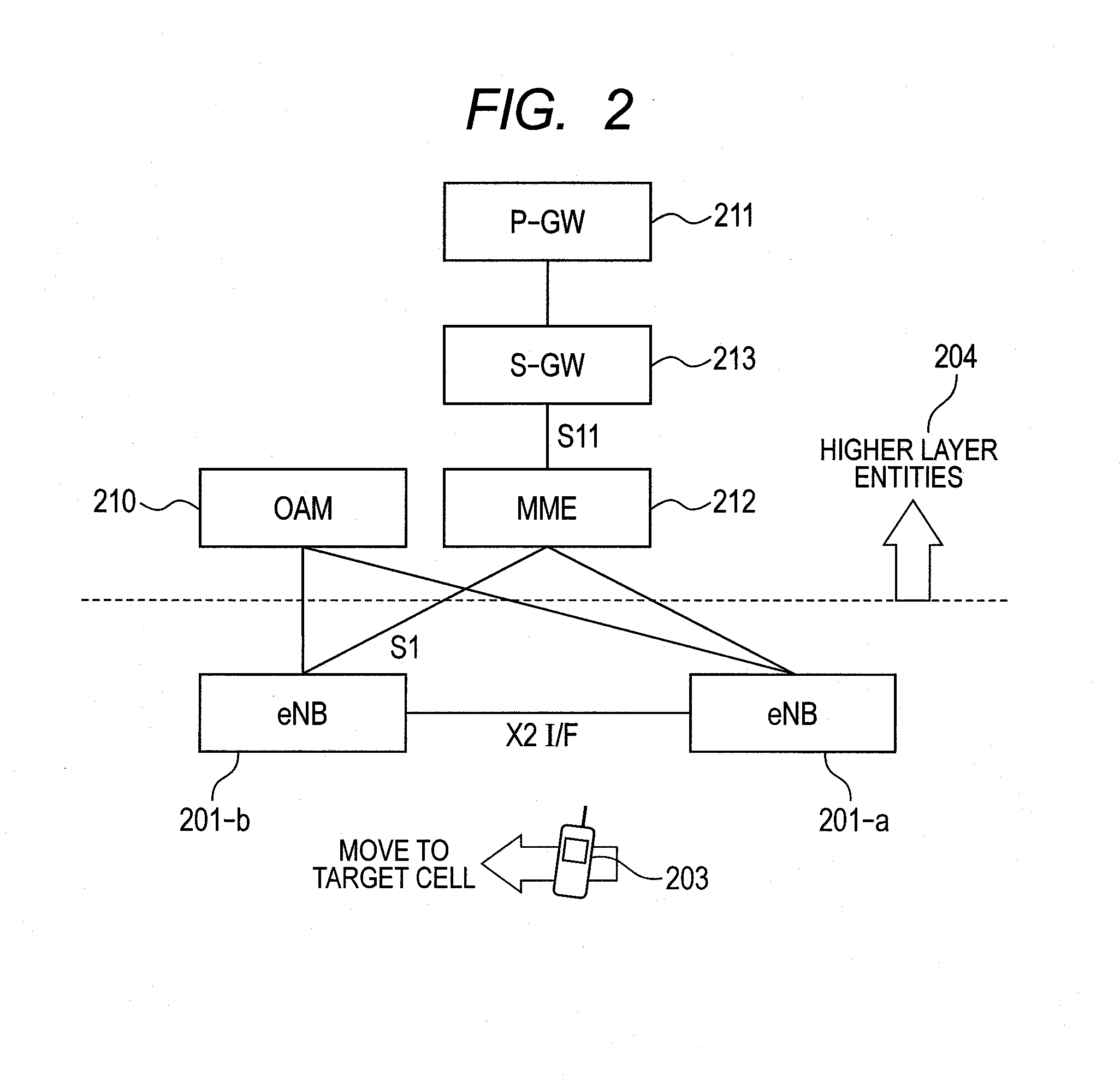
Specific examples of the E-UTRAN entity structure are shown in FIG. 2 and FIG. 3. FIG. 2 is a block diagram showing device connections relating to handovers among base stations monitored by a single MME (Mobile Management Entity) 212. FIG. 3 is a block diagram showing device connections relating to handovers among base stations by way of different MME.

Handovers made by the E-UTRAN can be broadly grouped into two types. In both cases the procedures for establishing the bearer connection are different but the processing between the terminal (UE) 203 and the base station 201-a is approximately the same.

The higher layer entity 204 utilized in the following description is a section or a collective name for the OAM (Operation And Maintenance) device 210, MME212, S-GW (Serving-GateWay), P-GW (Packet Data Network-GateWay). The OAM device 210 includes a base station control device (EMS: Element Management System).

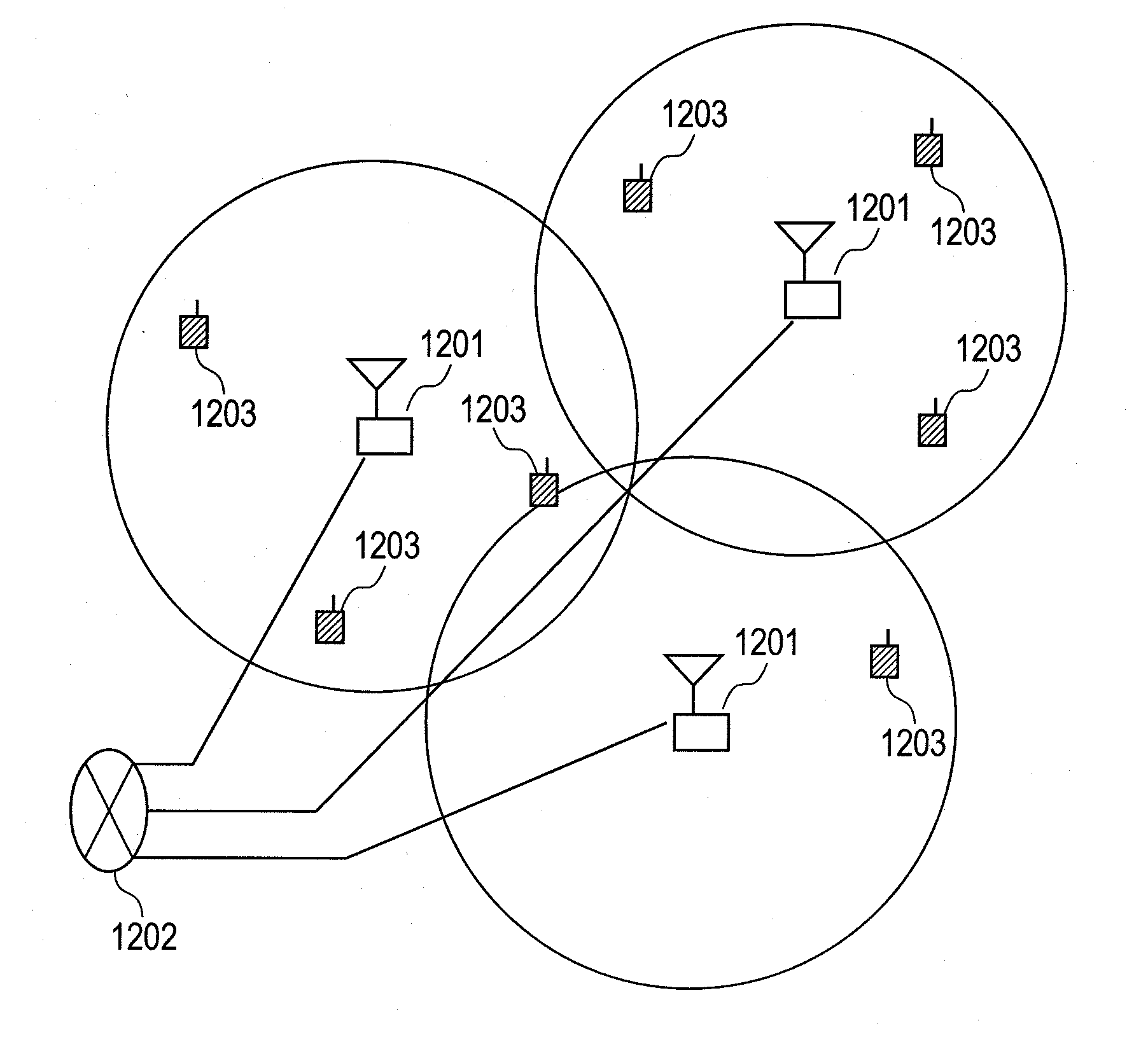
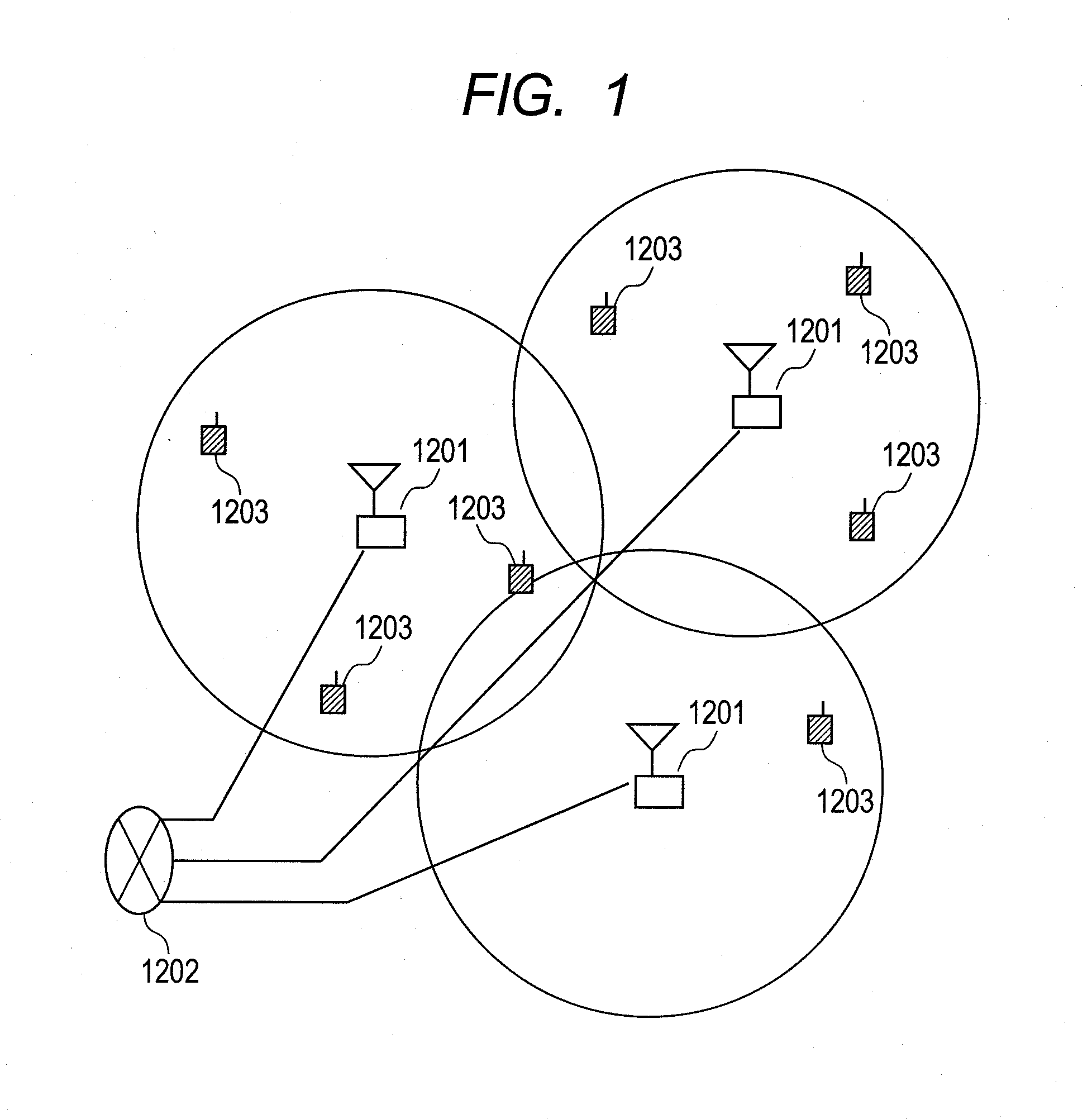
FIG. 25 is a diagram showing the structure of the wireless communication system...

second embodiment

The second embodiment is described next while referring to the sequence drawing shown in FIG. 19. The point where this embodiment differs from the first embodiment is that no interface is needed to directly exchange information between base stations but in all other points the embodiments are identical. This embodiment will for example likely prove applicable to femtocell base stations. Femtocell base stations are applicable because they can be connected to back haul lines provided to Internet Service Providers (ISP).

The following step 2102-b here replaces the process implemented in step 2102. In step 2102-b, the higher layer entity 204 serves as an intermediary to report interference information and load information that was reported by the inter-base station interface (such as the X2 interface for E-UTRAN). The upstream device 204 may for example report by way of an interface called the S1 interface in E-UTRAN that couples the base station and MME.

The higher layer entity 204 may a...

third embodiment

FIG. 20 is a drawing showing the handover sequence in the third embodiment. Among the process flows shown in FIG. 8 described in the first embodiment, the processing in step 2101 may be implemented as shown next. The terminal 203 may be set to report acquisition of cell size information from neighbor cells via the neighbor cell ID rather than via the upstream device 204 (step 2101-a). The type of neighbor cell can be identified from the reported cell ID by dividing up the range in which cell ID are allocated among femtocell and macrocell base stations. All other processing is the same as the first embodiment.

The hardware structure is implemented by the base station shown in FIG. 7, and the base station control device shown in FIG. 6.


PUM


Abstract

Interference applied to neighbor cells during terminal handovers can be reduced in wireless communication systems containing base stations having different cell sizes. A serving cell makes handover judgment criteria easier based on pre-acquired cell size information on its own cell and cell size information of neighbor cells in order to facilitate terminal handovers from a base station with a large cell size to a base station with a small cell size. The serving cell finds evaluation function values based on the propagation state (e.g. reference signal received power) between the terminal and target cell, and the interference and load information exchanged between the base stations, and selects the terminal for handover by comparing the evaluation function value with the handover criteria value. The system selects a target cell having a good effect in lowering interference such as a cell with large reference signal received power acquired from a terminal, to serve as the handover destination.

Description

CLAIM OF PRIORITYThe present application claims priority from Japanese patent application JP 2010-041495 filed on Feb. 26, 2010, the content of which is hereby incorporated by reference into this application.FIELD OF THE INVENTIONThe present invention relates to a mobility control method mitigating inter cell interference and base stations which adopt the method, and more particularly to abase station, a wireless communication system and a mobility control method mitigating inter cell interference including mobility control technology for mitigating inter cell interference in cellular wireless communication systems using OFDMA (Orthogonal Frequency Division Multiple Access).BACKGROUND OF THE INVENTIONThe structure of a typical cellular wireless communication system is described next while referring to the concept diagram in FIG. 1. In a cellular wireless system, the wireless base stations 1201 cover an area called a cell. The cell may be called by names such as a target cell; microc...

Claims


Application Information

Patent Timeline
IPC IPC(8): H04W36/00
CPCH04W36/20H04W36/0083H04W36/0085H04W36/00837
Inventor YAMAMOTO, TOMONORITAMAKI, SATOSHIKATAYAMA, RINTAROISHII, HIROTAKE
Owner GK BRIDGE 1
Why Eureka
Try Eureka