

Packet relay device
a packet relay and relay technology, applied in data switching networks, high-level techniques, sustainable buildings, etc., can solve the problems of sacrificing the continuity of communication, the power consumption of packet relay devices in japan in 2025 is estimated to be 13 times more, and the simple saving of power in a packet relay device sacrifices the continuity of communication. , to achieve the effect of reducing standby power consumption
- Summary
- Abstract
- Description
- Claims
- Application Information
AI Technical Summary
Benefits of technology
Problems solved by technology
Method used
Image

Examples
first embodiment
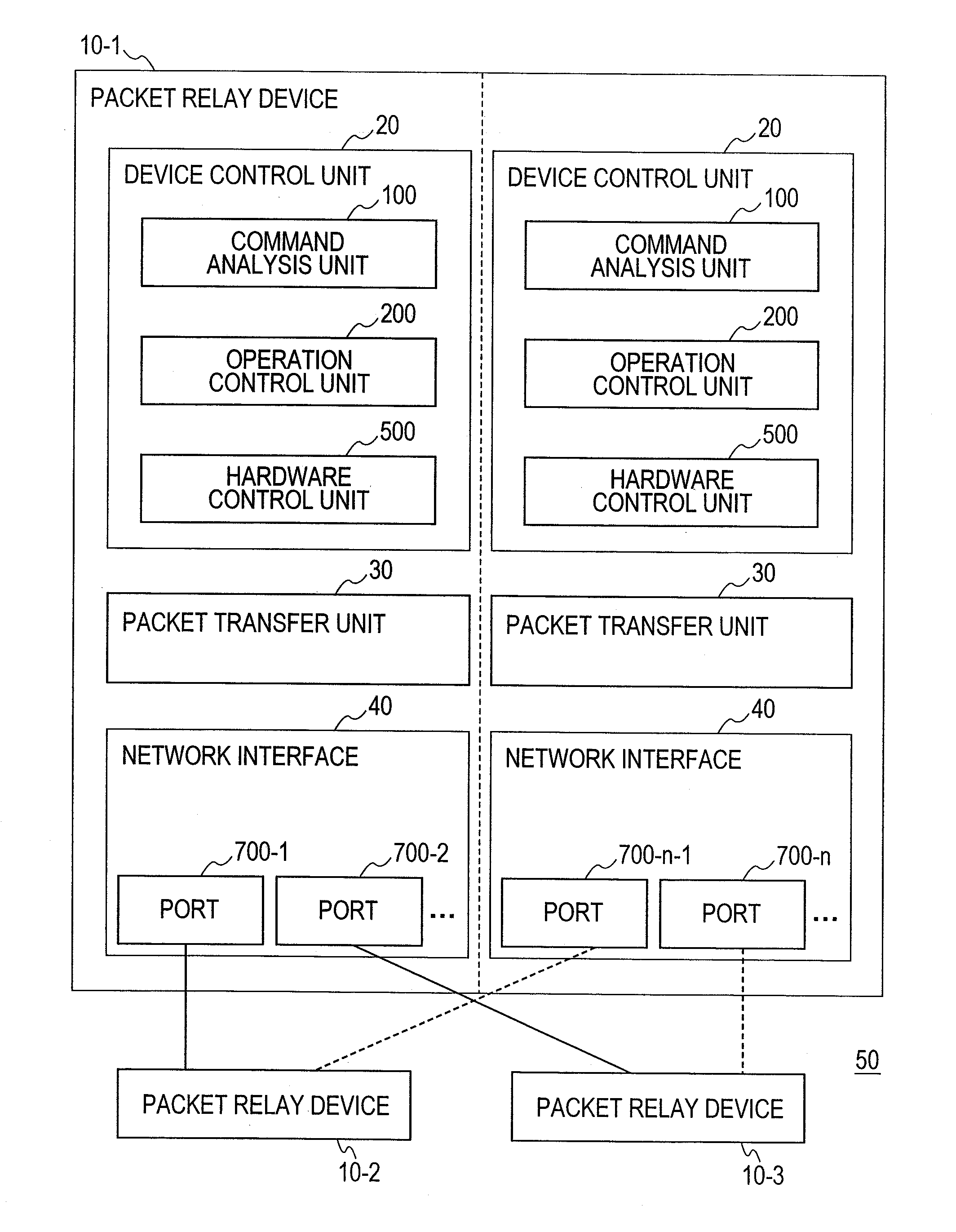
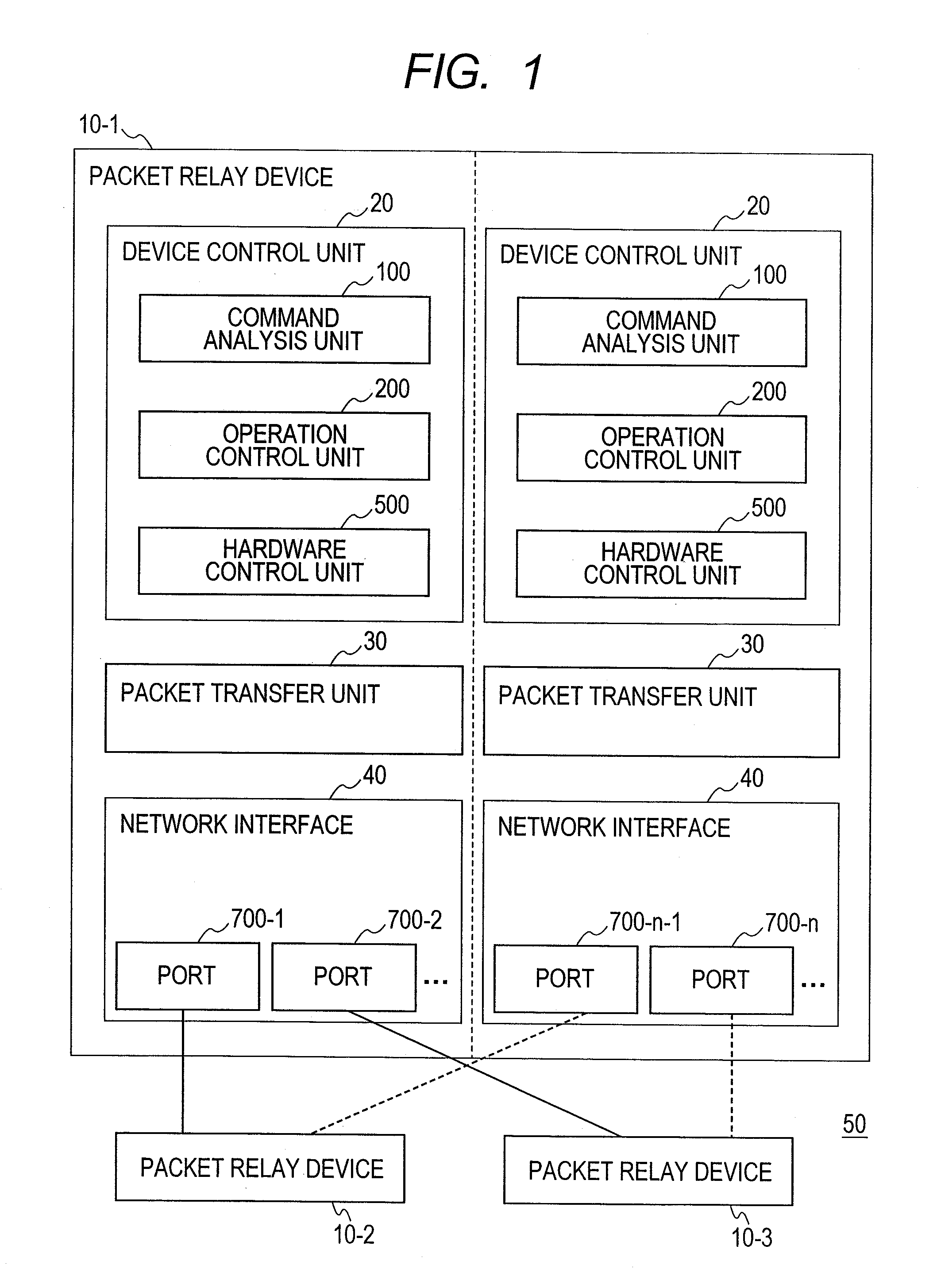
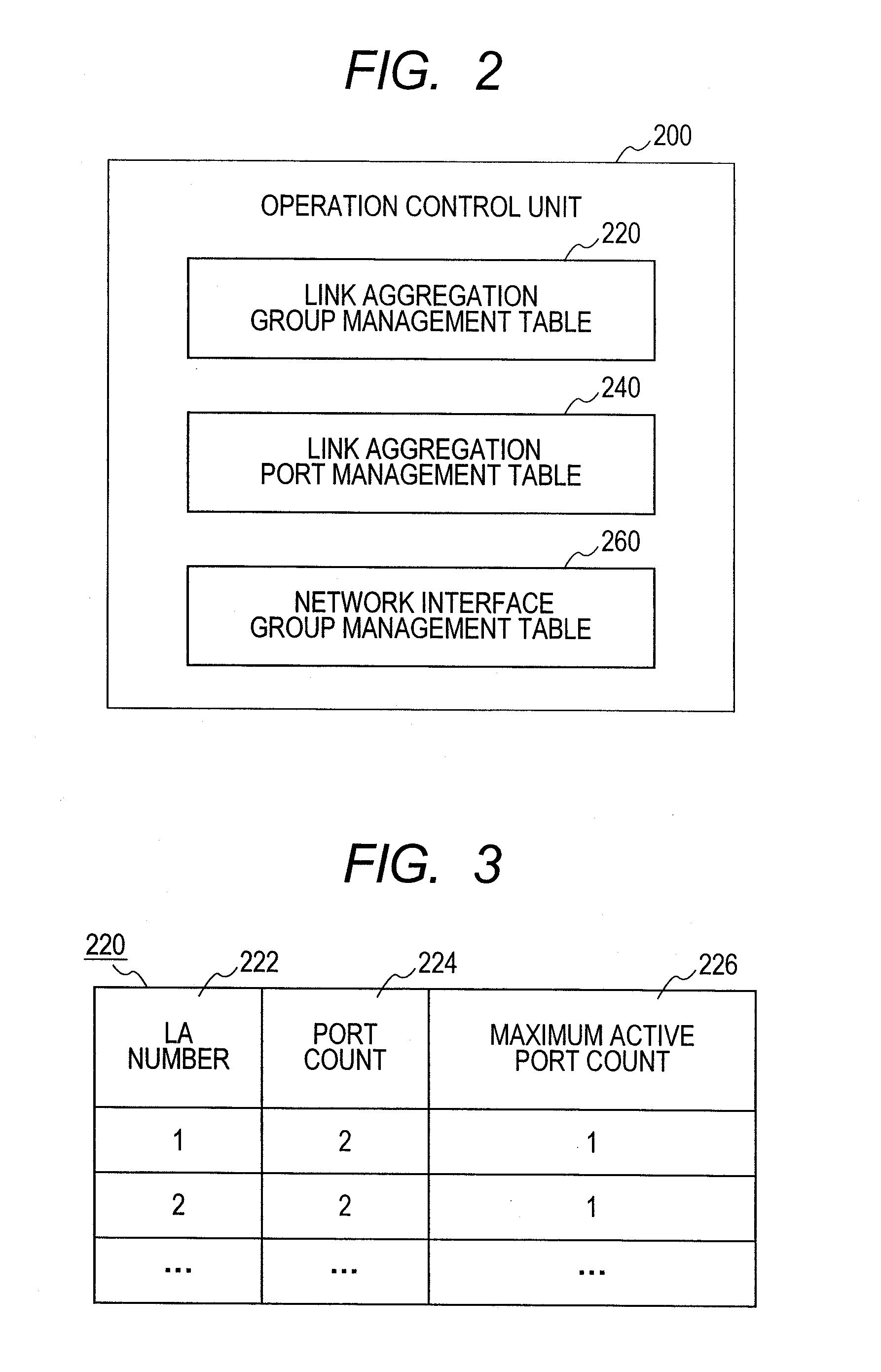
[0067]Referring to FIGS. 6 and 8, the process flow according to the first embodiment will be described. In the first embodiment, each packet relay device 10 controls the power supply to the network interfaces 40 in accordance with the port state of the link aggregation using the group management table 220, the port management table 240, and the group management table 260.
[0068]To make the ports and the network interfaces redundant, the user previously sets up the configuration of each packet relay device 10. Specifically, to set up a link aggregation for making the ports redundant requires setting of an LA number for identifying a link aggregation, NIF numbers and port numbers belonging to the LA number, a maximum active port count representing the maximum number of ports that are activated among ports belonging to the LA number, and LA priority levels that represent priority levels on the basis of which ports will be placed on standby. If there are multiple link aggregations, it is...
second embodiment
[0084]A second embodiment of the present invention will be described with reference to FIGS. 9 to 18. In the second embodiment, the packet relay device 10 performs control so that the ports 700 and the network interfaces 40 are placed in the optimum state, by using a total traffic volume management table 280, a port traffic volume management table 300, a traffic volume upper limit management table 320, and a group management table 340 to be described later and in accordance with a change in traffic volume of each link aggregation.
[0085]First, referring to FIG. 9, an operation control unit 200A according to the second embodiment will be described. In FIG. 9, the operation control unit 200A holds the link aggregation total traffic volume management table 280, the link aggregation port traffic volume management table 300, the link aggregation traffic volume upper limit management table 320, and the network interface group management table 340. The operation control unit 200A refers to ...
third embodiment
[0105]A third embodiment of the present invention will be described with reference to FIGS. 19 to 27. In the third embodiment, an operation control unit 200B of the packet relay device 10 uses a port check status management table 400 and a group management table 420, and the hardware control unit 500 uses a check result management table 520 and a check criteria table 540. Thus, the packet relay device 10 reduces the communication interruption time caused by intermittent occurrence of failures in active ports and therefore performs control so that the ports and the network interfaces are placed in the optimum state.
[0106]First, referring to FIG. 19, the operation control unit 200B will be described in detail. In FIG. 19, the operation control unit 200B holds the link aggregation port check status management table 400 and the network interface group management table 420. The operation control unit 200B refers to the link aggregation port check status management table 400 and the netwo...
PUM
 Abstract
Description
Claims
Application Information