
System for indicating an airplane hard landing

Active Publication Date: 2011-09-08
THE BF GOODRICH CO
View PDF12 Cites 27 Cited by
  • Summary
  • Abstract
  • Description
  • Claims
  • Application Information

AI Technical Summary

Benefits of technology

[0006]The present invention relates to an indication system as described herein in accordance with the illustrated embodiments, which may be used in conjunction with a pressure transducer located within a high pressure chamber of a shock strut, to indicate that a hard landing event has indeed been experienced by the aircraft. Accordingly, a noted advantage of the invention is a reduction in the number of costly inspections for the airlines subsequent to a hard landing event.
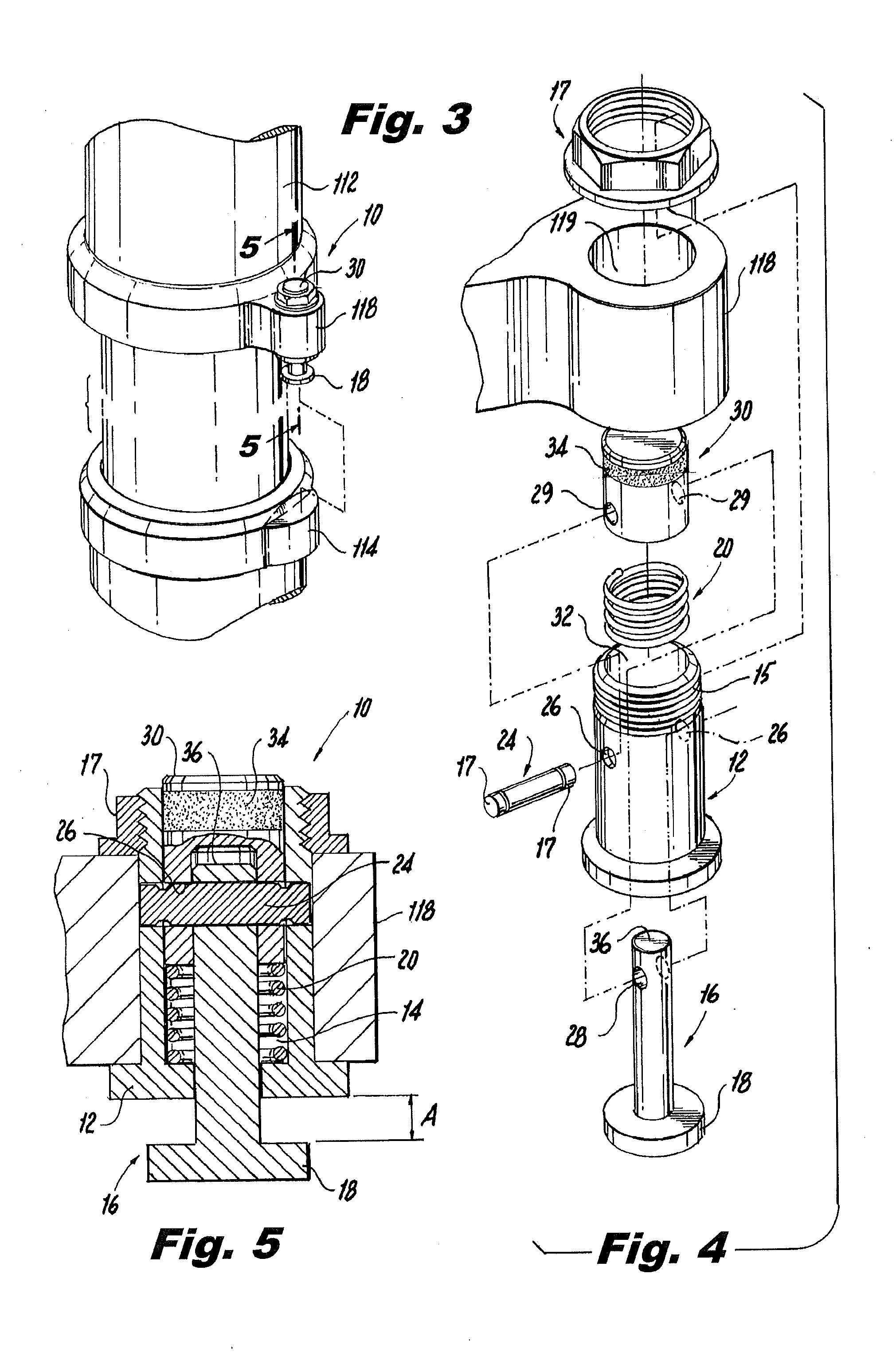
[0007]Generally, in one illustrated embodiment, the indication system is contained within a housing that is preferably separable relative to the outer cylinder of a landing gear shock strut assembly so that it may be moved away for maintenance activity. The indication system includes an actuator member, such as a plunger, that is movable based on a detected load and stroke within the shock strut assembly. In an additional embodiment, a secondary system may be utilized to measure the high pressure chamber of a shock strut or within another component of the landing gear system. This detected pressure may be used to determine the impact of the occurrence of the hard landing event experienced by the aircraft. Upon the occurrence of the hard landing event, the actuator member strokes by an amount sufficient to cause a component such as shear pin to physically shear (e.g., fracture). A compression spring, for example, then urges an indicator into an indicating position, which preferably is a position that is readily visible by a pilot, ground personnel or another walking around the aircraft. It is noted the compression spring urges the indicator from its non-indicating position into an indicating position and maintains it in this position preferably until the fractured shear pin has been replaced. The spring force is designed so as to prevent the plunger head from being physically forced back into the housing.
[0008]In one aspect of the invention according to an illustrated embodiment, what is provided is a device mounted to a portion of an aircraft landing gear for indicating occurrence of a hard landing of an aircraft. The device includes a housing preferably mounted to a portion of an aircraft landing gear strut assembly. This housing member may also be configured and operative to pivot outwardly relative to the landing gear shock strut assembly. The housing member preferably includes an indicator member movable from a first position to a second position such that when moved to the second position the indicator member is configured to indicate occurrence of a hard landing for the aircraft and at least a portion of the indicator member extends outwardly from the housing member when in it's second position. Further provided is an elongated actuator member movable from a first position to a second position configured and operative such that when the elongated actuator member moves to the second position it causes the indicator member to move to it's second position, and when positioned in it's first position, at least a portion of the elongated actuator member extends outwardly from the housing member. Also provided is a releasing member operatively coupled to the elongated actuator member configured to be in a first state when the elongated actuator member is in it's first position and a second state permitting said elongated member to move to it's second position upon the occurrence of a hard landing for the aircraft. Operatively coupled to the indicator mechanism is a biasing mechanism for causing the indicator member to be maintained in it's second position after the elongated actuator member is moved to it's second position.
[0009]In another aspect of the invention according to another illustrated embodiment, what is provided is an indicator member movable from a first position to a second position such that when moved to it's second position the indicator member is configured to indicate occurrence of a hard landing for an aircraft. Further provided is an elongated actuator member movable from a first position to a second position configured and operative such that when the elongated member moves to it's second position it causes the indicator member to move to it's second position. The elongated actuator member has an intermediate portion and first and second end regions wherein the intermediate portion of the elongated actuator member is pivotally coupled to a portion of the aircraft landing gear such that the first end region of the elongated actuator member is caused to pivot outwardly relative to a portion of the aircraft landing gear when the elongated actuator member is caused to move to it's second position. Additionally provided is a releasing member operatively coupled to the first end region of the elongated actuator member configured to be in a first state when the elongated actuator member is in it's first position and a second state permitting said elongated member to move to it's second position upon the occurrence of a hard landing for the aircraft. The indicator member further includes a biasing assembly for causing the first end region of the elongated actuator member to pivot outwardly relative to a portion of the aircraft landing gear when the elongated actuator member is caused to move to it's second position.

Problems solved by technology

Aircraft landing gear often are subject to excess energy typically being driven into it's strut assembly resulting in both bottoming the strut as well as exceeding structural limitations on the attached hardware.
This often constitutes a hard landing event or some other potential overloading activity.
In present systems, this type of end-of-limit indicator is not readily visible and the triggering of such a indicator may not necessarily or accurately indicate whether an event did occur.
Consequently, the fallback position for the airlines in such a situation is to perform an often unwarranted fully detailed inspection of the landing gear system.
However, this detection of the loads being exceeded, based only on the subjective determination of the pilot, is often unreliable.
In effect, the reactions perceived at the level of the flight deck often do not accurately convey the real load level applied to the aircraft as a whole.
That being so, a significant number of inspections, technically not justified, are invoked by the pilot, which entails inefficient use of time and superfluous expense, heavily penalizing the airline concerned.
In this case, no inspection is invoked although the aircraft structure could have been damaged, which can then entail grave and irremediable consequences during subsequent flights.

Method used


Image

  • System for indicating an airplane hard landing
  • System for indicating an airplane hard landing
  • System for indicating an airplane hard landing

Examples


Embodiment Construction

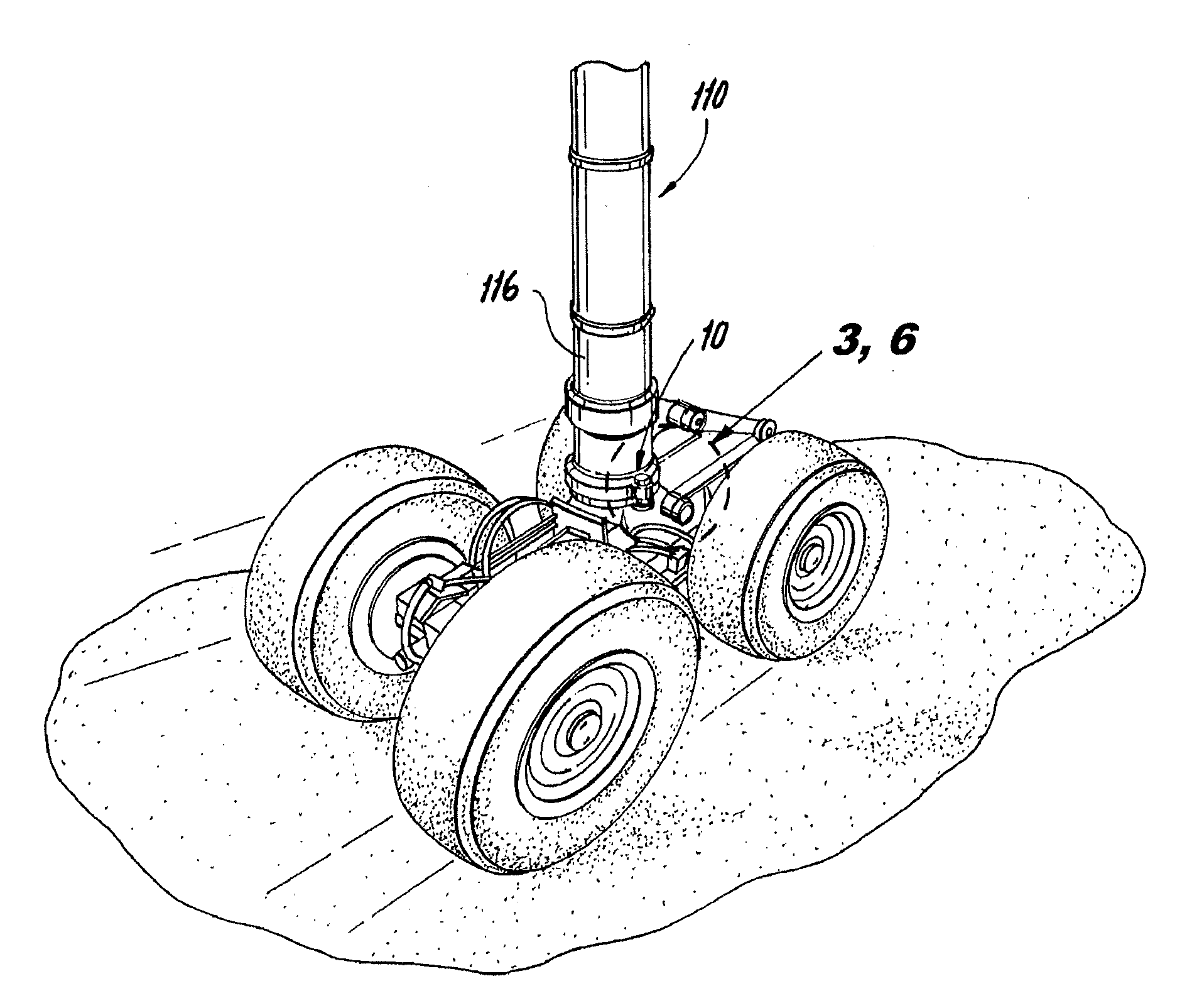
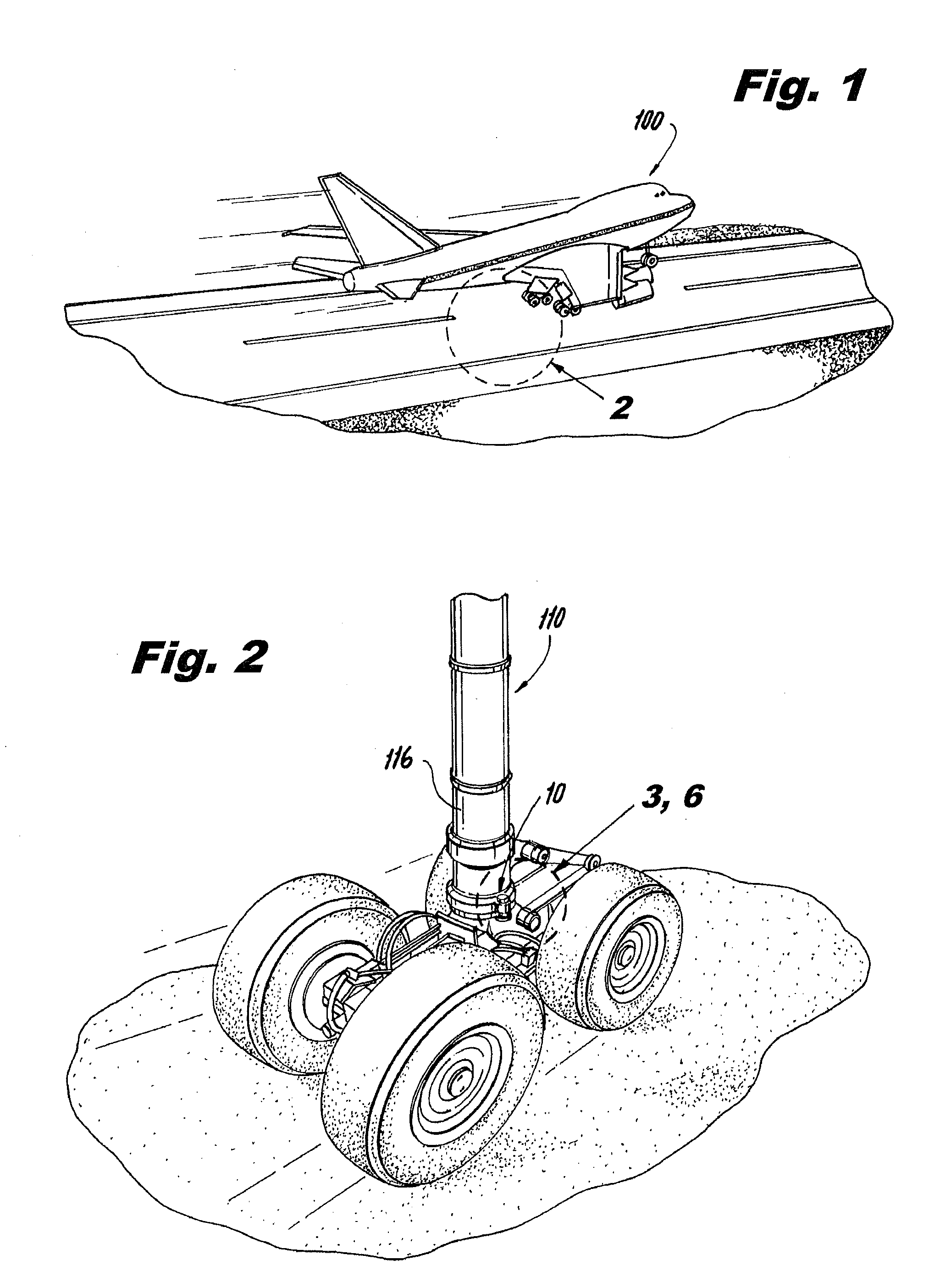
[0028]The present invention is now described more fully with reference to the accompanying drawings, in which an illustrated embodiment of the present invention is shown. The present invention is not limited in any way to the illustrated embodiments as the illustrated embodiments described below are merely exemplary of the invention, which can be embodied in various forms, as appreciated by one skilled in the art. Therefore, it is to be understood that any structural and functional details disclosed herein are not to be interpreted as limiting, but merely as a basis for the claims and as a representative for teaching one skilled in the art to variously employ the present invention. Furthermore, the terms and phrases used herein are not intended to be limiting but rather to provide an understandable description of the invention.

[0029]As will be apparent from the below description in accordance with an illustrated embodiment depicted in FIGS. 1-7, the present invention is to be apprec...


PUM


Abstract

An indicator assembly for an aircraft landing gear for providing indication of a hard landing. The indicator assembly including a actuator member movable when the pressure on a shock strut of the aircraft landing gear exceeds a desired load and stroke threshold indicative of a hard landing. A shear pin is coupled to the actuator member which is configured to shear when a desired level of force is applied to at least a portion of the shear pin. A visibly recognizable indictor is moved from a non-indicating position to an indicating position upon shearing of the shear pin.

Description

FIELD OF THE INVENTION[0001]This invention relates to an indication system for use with an aircraft landing gear system, and more specifically to an indication system that provides a readily visible indicator after the occurrence of an aircraft hard landing.BACKGROUND OF THE INVENTION[0002]Aircraft landing gear often are subject to excess energy typically being driven into it's strut assembly resulting in both bottoming the strut as well as exceeding structural limitations on the attached hardware. This often constitutes a hard landing event or some other potential overloading activity.[0003]Airlines are required to fully inspect the landing gear and aircraft if a hard landing event has occurred or has been suspected of occurring. Presently, what is often used to determine whether a hard landing event has occurred is reliance upon the pilot's senses (e.g., feels, hears or possibly sees) during flight, especially during landing and takeoff. Thus, if the pilot feels an unusually large...

Claims


Application Information

Patent Timeline
IPC IPC(8): G01L5/00
CPCB64C25/001B64D2045/008B64D45/00B64C25/60
Inventor MARTIN, DENNIS W.ACKS, JAMES P.
Owner THE BF GOODRICH CO
Learn More