Variable valve timing apparatus for internal combustion engine

a technology of variable valve timing and internal combustion engine, which is applied in the direction of valve arrangement, mechanical equipment, machines/engines, etc., can solve the problem of low amount and achieve the effect of suppressing any adverse effect of variable valve timing performan

Inactive Publication Date: 2011-09-08
TOYOTA JIDOSHA KK +1
View PDF4 Cites 18 Cited by
  • Summary
  • Abstract
  • Description
  • Claims
  • Application Information

AI Technical Summary

Benefits of technology

[0017]This invention therefore provides a variable valve timing apparatus for an internal combustion engine that is capable of reliably fixing valve timing at an intermediate angle by a lock mechanism during engine startup after the engine has been stopped without the valve timing being fixed, should such a event occur, while suppressing any adverse effects on variable valve timing performance.
[0020]Therefore, with this invention, when both of the rotating bodies stop rotating at a given phase when the engine stops, the opening mechanism places at least one of the hydraulic pressure chambers that is communicated with the discharge passage in a position vertically higher than the rotational axis when the first rotating body and the second rotating body have stopped rotating at a given phase, and from which hydraulic fluid is discharged into the discharge passage, in a state constantly open to ambient air regardless of the phase at which the rotating bodies have stopped. As a result, ambient air is introduced into the hydraulic pressure chambers that are open to the ambient air, and the hydraulic fluid in the hydraulic pressure chambers is discharged through the discharge passages according to the amount of introduced ambient air. As a result of the hydraulic fluid being discharged from the hydraulic pressure chambers in this way, the hydraulic pressure in the hydraulic pressure chambers that acts on the vane is reduced, thereby making it easier for the vane to rock. Accordingly, the amount that the second rotating body pivots is able to increase. Also, this opening mechanism communicates the hydraulic pressure chamber with the ambient air space at least when both of the rotating bodies are stopped, i.e., the hydraulic pressure chamber is maintained tightly closed (i.e., oil tight) while the engine operating unless there is some other control command, so hydraulic fluid is not discharged. In this way, it is possible to reliably fix the valve timing at the intermediate angle with the lock mechanism when the engine is started, while suppressing adverse effects on variable valve timing performance.

Problems solved by technology

However, even though the amount that is discharged from the hydraulic pressure is affected by how tightly closed the hydraulic pressure chamber is (i.e., the oil tightness of the hydraulic pressure chamber), that amount is low.

Method used


Image

  • Variable valve timing apparatus for internal combustion engine
  • Variable valve timing apparatus for internal combustion engine
  • Variable valve timing apparatus for internal combustion engine

Examples


first example embodiment

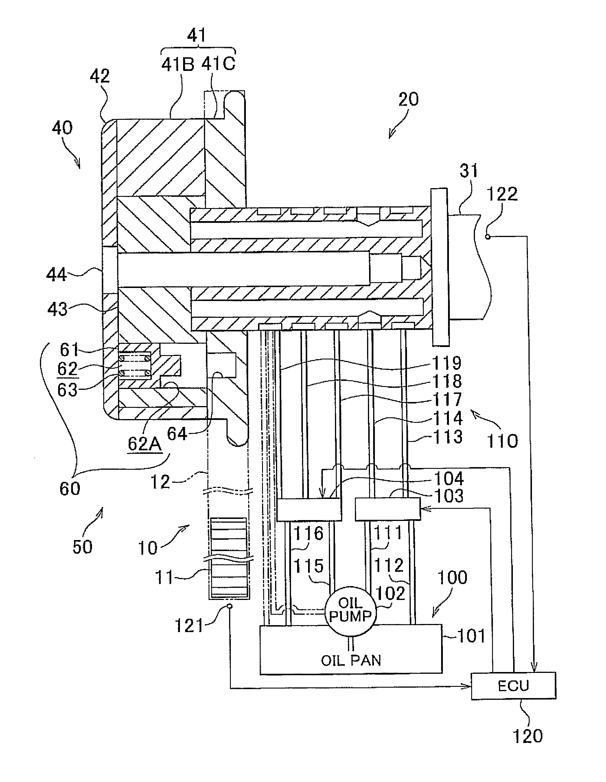
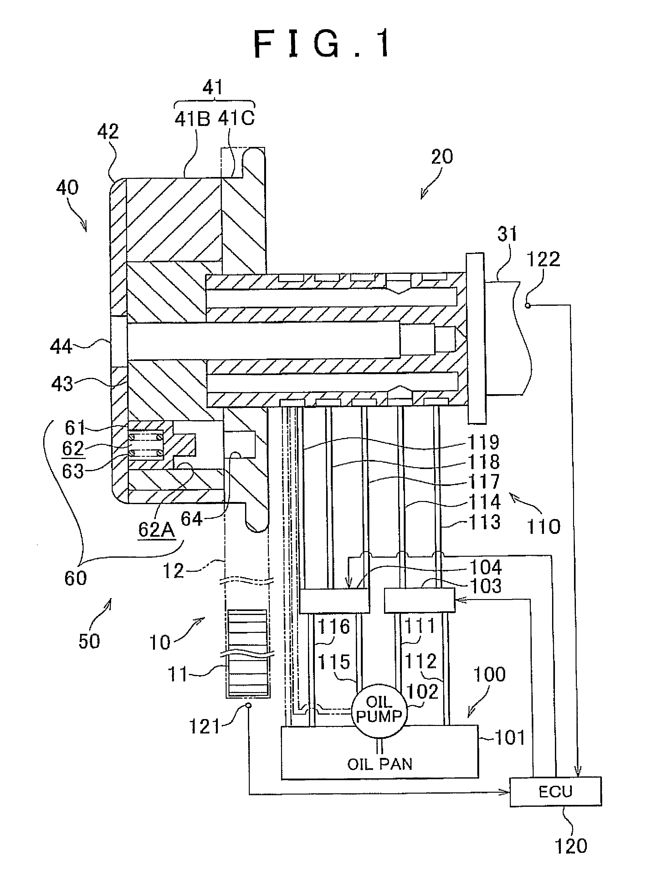
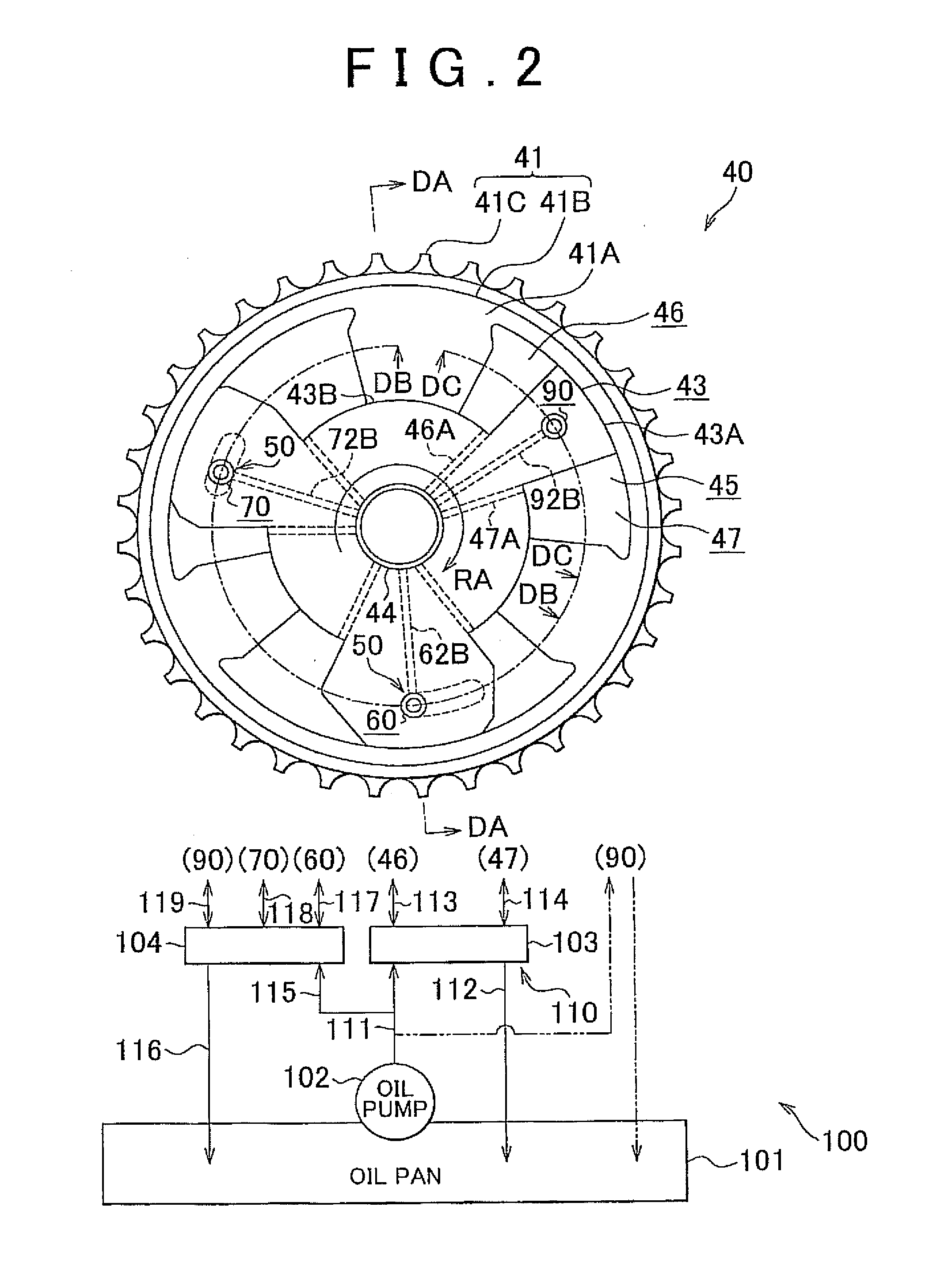
[0033]A first example embodiment of the variable valve timing apparatus for an internal combustion engine of the invention, in which this variable valve timing apparatus is one that changes the valve timing of an intake valve, will be described with reference to FIGS. 1 to 6. Incidentally, in the description below, the term “valve timing” refers to the valve timing of the intake valve unless otherwise specified.

[0034]As shown in FIG. 1, an oil pan 101 in which hydraulic fluid for driving various hydraulically driven auxiliary devices is stored is mounted to a lower portion of an internal combustion engine 10. Meanwhile, a camshaft 31 for driving an intake valve, not shown, open and closed is provided in an upper portion of the internal combustion engine 10, and a variable valve timing apparatus 20 for changing the valve timing is provided on this camshaft 31. The rotational force of a crankshaft 11 is transmitted from a chain 12 to the camshaft 31 of the intake valve via the variabl...


PUM


Abstract

A variable valve timing apparatus includes a variable valve timing mechanism that includes a first rotating body and a second rotating body that are rotating bodies that rotate about the same rotational axis; advance chambers and retard chambers that serve as hydraulic pressure chambers into which hydraulic fluid is supplied from an oil pump; and a discharge passage that discharges hydraulic fluid from the hydraulic pressure chambers. At least one of the hydraulic pressure chambers that is communicated with the discharge passage in a position vertically higher than the rotational axis when the first rotating body and the second rotating body have stopped rotating at a given phase, and from which hydraulic fluid is discharged into the discharge passage, is placed in a state constantly open to ambient air regardless of the phase at which the first rotating body and the second rotating body have stopped.

Description

INCORPORATION BY REFERENCE[0001]The disclosure of Japanese Patent Application No. 2010-048139 filed on Mar. 4, 2010, including the specification, drawings and abstract is incorporated herein by reference in its entirety.BACKGROUND OF THE INVENTION[0002]1. Field of the Invention[0003]The invention relates to a variable valve timing apparatus for an internal combustion engine, that is provided with a variable valve timing mechanism that changes the valve timing of an intake valve and an exhaust valve, a lock mechanism that fixes the valve timing at an intermediate angle between a most retarded angle and a most advanced angle, and a discharge passage that extends from an advance chamber and a retard chamber to a rotational axis side of a camshaft and that enables hydraulic fluid to be discharged from each chamber.[0004]2. Description of the Related Art[0005]One variable valve timing apparatus for an internal combustion engine that has been put into practical use rotates a first rotatin...

Claims


Application Information

Patent Timeline
Patent Type & Authority Applications(United States)
IPC IPC(8): F01L1/34
CPCF01L1/34F01L1/3442F01L2001/34469F01L2001/34453
Inventor YAMAGUCHI, TAKASHINUMAKURA, MASAKIYOKOYAMA, YUU
Owner TOYOTA JIDOSHA KK
Why Eureka
Try Eureka