Rotary die bonding apparatus and methodology thereof

Inactive Publication Date: 2011-09-08
SIM AH YOONG
View PDF0 Cites 9 Cited by
  • Summary
  • Abstract
  • Description
  • Claims
  • Application Information

AI Technical Summary

Benefits of technology

[0015]It is yet another object of the present invention to provide a rotary die bonding apparatus whereby the vertical motion actuator (104)

Problems solved by technology

Among the limitations and deficiencies of the above inventions is the vibration on said apparatus during performance of each task.
Current reciprocal design will increase vibration when speed increases, thus affecting the operation accuracy o

Method used


Image

  • Rotary die bonding apparatus and methodology thereof
  • Rotary die bonding apparatus and methodology thereof
  • Rotary die bonding apparatus and methodology thereof

Examples


Example

5. DETAILED DESCRIPTION OF THE DRAWINGS

[0032]In the following detailed description, numerous specific details are set forth in order to provide a thorough understanding of the invention. However, it will be understood by those or ordinary skill in the art that the invention may be practiced without these specific details. In other instances, well known methods, procedures and / or components have not been described in detail so as not to obscure the invention.

[0033]The invention will be more clearly understood from the following description of the embodiments thereof, given by way of example only with reference to the accompanying drawings which are not drawn to scale.

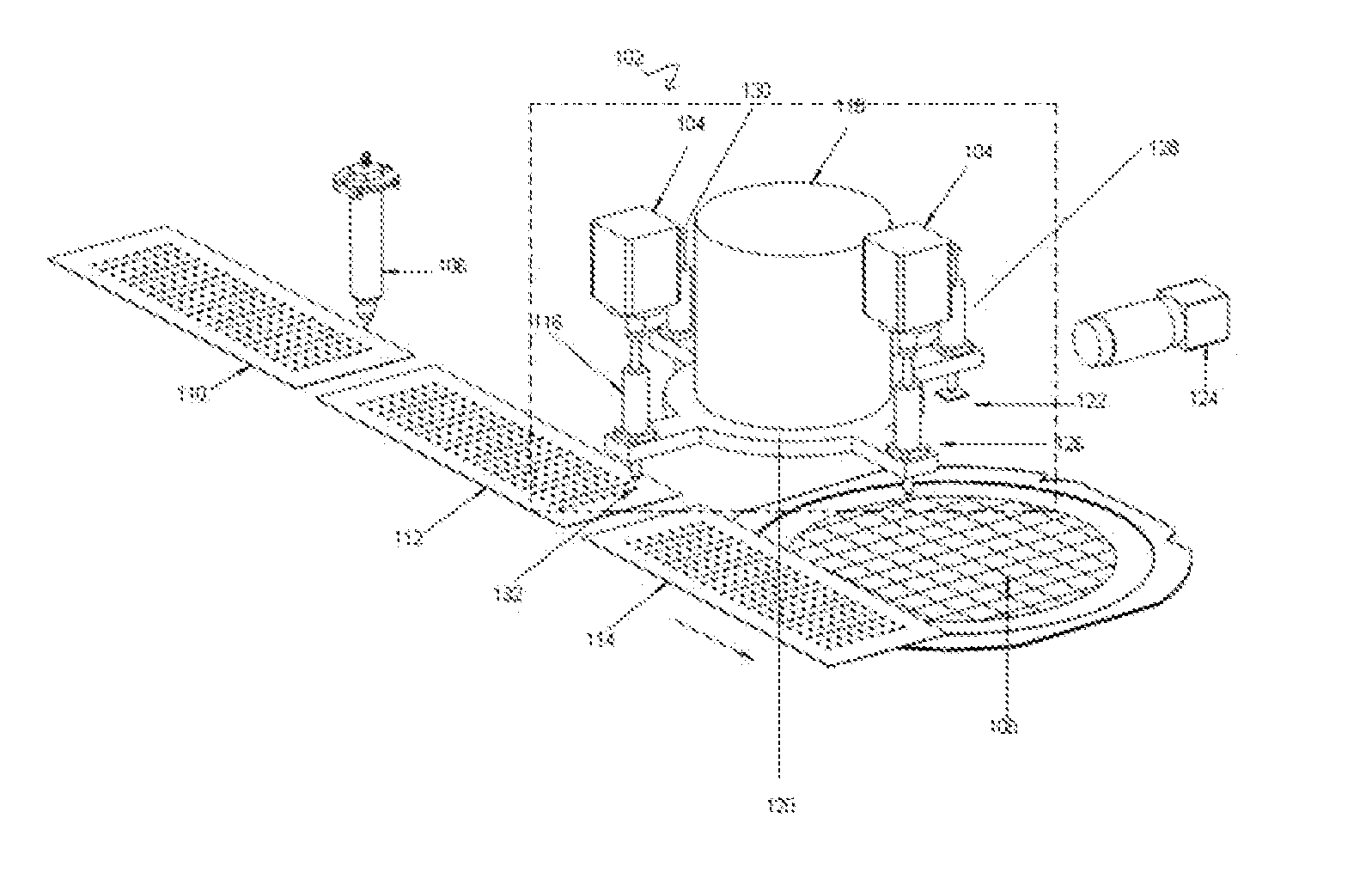
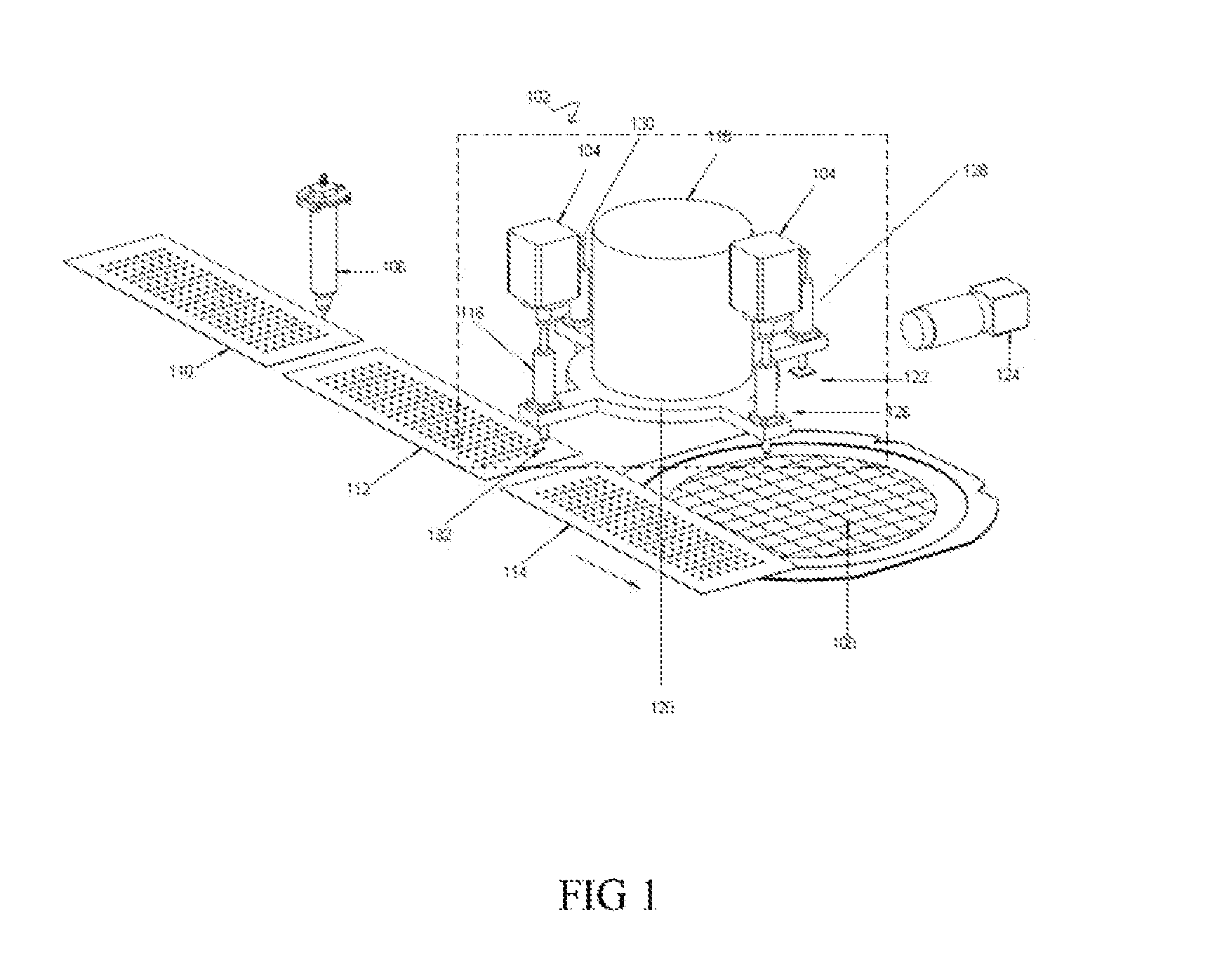
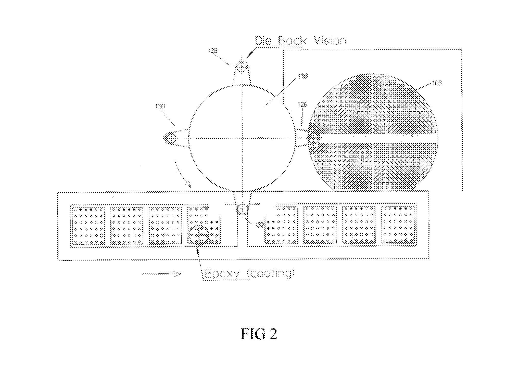
[0034]Referring to FIG. 1, there is shown a perspective view of the rotary die bonding apparatus (102) together with the image capturing apparatus (124), epoxy syringe (106), die wafer ring (108) and the lead frame (112, 114); further substantiated by FIG. 2, showing a top view of the rotary die bonding apparatus (102). ...


PUM

PropertyMeasurementUnit
Distanceaaaaaaaaaa
Circumferenceaaaaaaaaaa

Abstract

The present invention relates generally to a rotary die bonding apparatus (102) comprising a vertical motion linear actuator and a rotary motion actuator with a plurality of pick up heads (116) for transferring semiconductor die (122) from diced wafer to the lead frame for die bonding process, wherein said plurality of pick up heads (116) performs its assigned task such as pick (126), die bonding (132), inspection (128) and others simultaneously upon reaching its specific location and rotates to another location upon completion of each task to perform the next assigned task.

Description

1. TECHNICAL FIELD OF THE INVENTION[0001]The present invention relates generally to a rotary die bonding apparatus comprising a vertical motion linear actuator and a rotary motion actuator system with a plurality of pick up heads for transferring semiconductor die from diced wafer to the lead frame for die bonding process, wherein said plurality of pick up heads performs its assigned task such as pick, die bonding, inspection and others simultaneously upon reaching its specific location and rotates to another location upon completion of each task to perform the next assigned task.2. BACKGROUND OF THE INVENTION[0002]Generally, after a semiconductor die is being separated from the semiconductor wafer, or in other words, wafer dicing, said die will stay at the dicing tape until it is being handled or extracted by a die handling apparatus such as a die bonder or die sorter. Said die handling apparatus performs tasks such as die attach, whereby said die picked up from, the said wafer and...

Claims


Application Information

Patent Timeline
IPC IPC(8): B23K31/02B23K37/00
CPCH01L21/67144H01L24/75H01L24/83H01L2224/2919H01L2224/83H01L2924/01033H01L2924/01082H01L2224/838H01L2924/0665H01L2924/01006H01L2924/00
Inventor SIM, AH YOONG
Owner SIM AH YOONG
Why Eureka
Try Eureka