Driving type patient platform, control device for driving type patient platform, control program for driving type patient platform, and particle beam therapy system utilizing these items

Active Publication Date: 2011-09-08
MITSUBISHI ELECTRIC CORP
View PDF5 Cites 25 Cited by
  • Summary
  • Abstract
  • Description
  • Claims
  • Application Information

AI Technical Summary

Benefits of technology

[0010]The objective of the present invention is to obtain a driving type patient platform in which there can efficiently be performed the po

Problems solved by technology

In the positioning work, while the position of a diseased site is being monitored by an X-ray image-capturing device, the angle adjustment for a treatment table is implemented in such a way that a particle beam is irradiated onto the diseased site along a direction determined at the stage of making a treatment plan; however, because t

Method used


Image

  • Driving type patient platform, control device for driving type patient platform, control program for driving type patient platform, and particle beam therapy system utilizing these items
  • Driving type patient platform, control device for driving type patient platform, control program for driving type patient platform, and particle beam therapy system utilizing these items
  • Driving type patient platform, control device for driving type patient platform, control program for driving type patient platform, and particle beam therapy system utilizing these items

Examples


embodiment 1

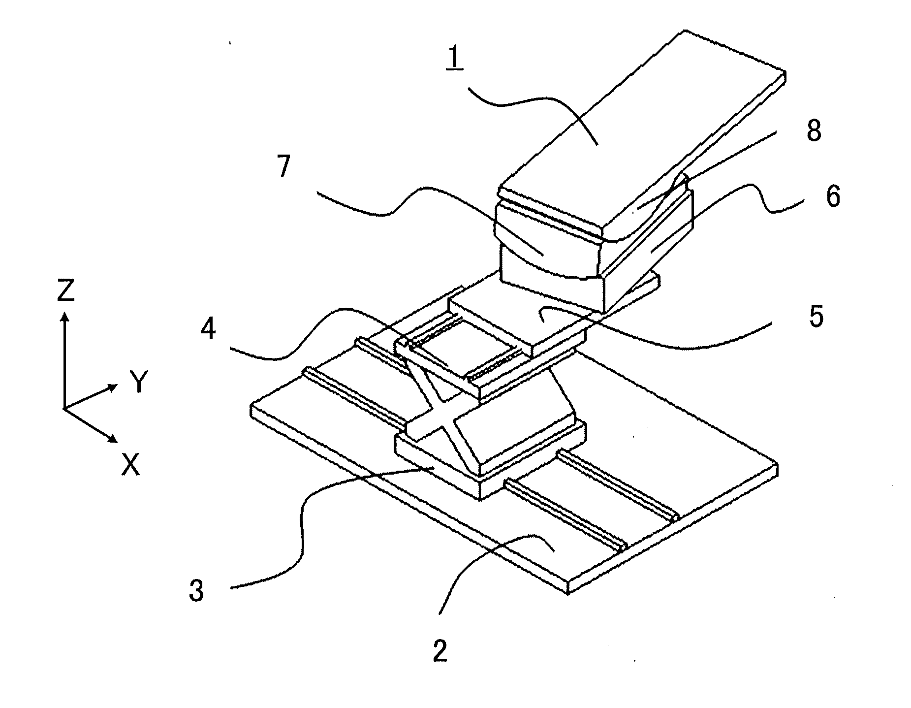
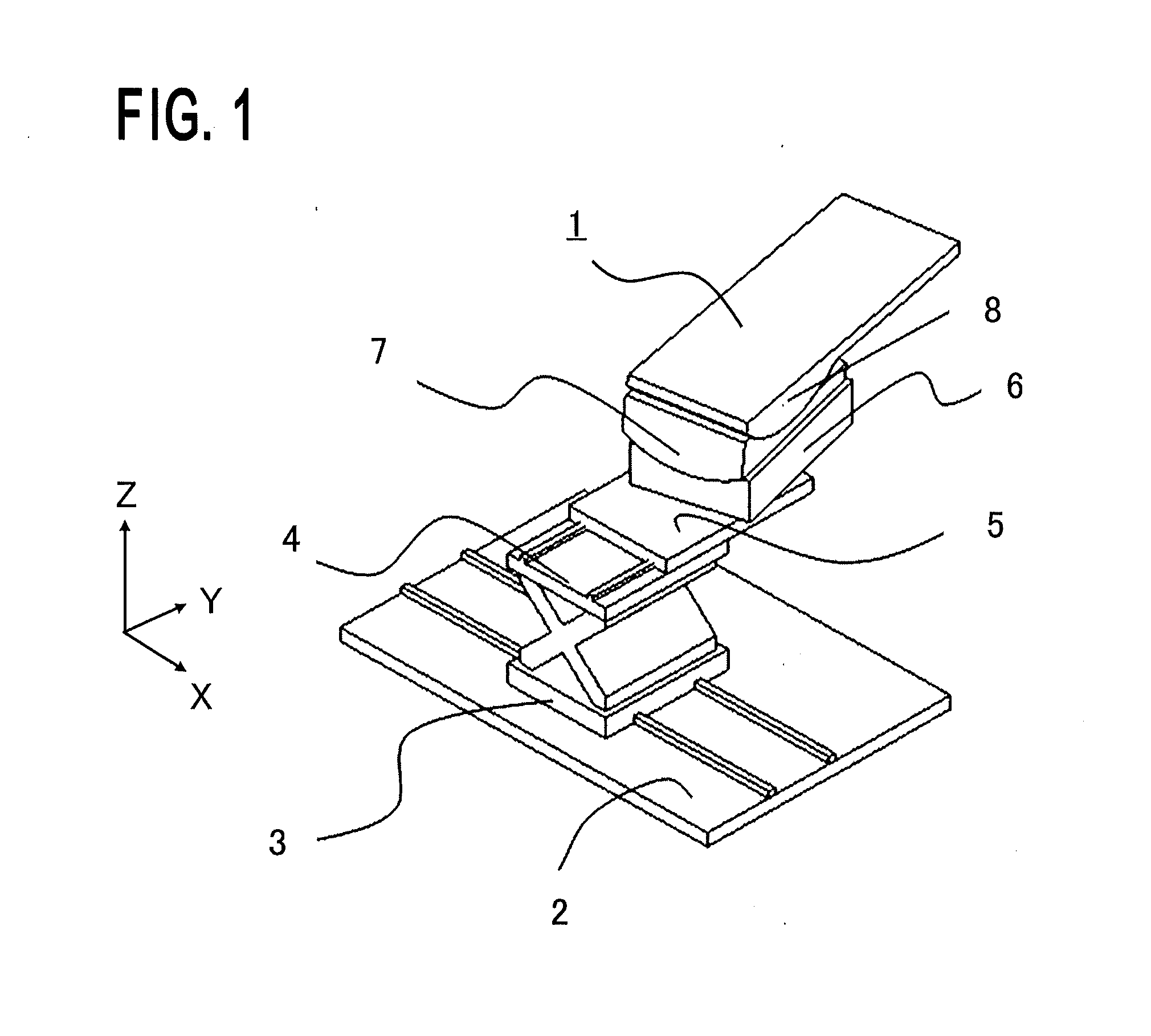
[0032]FIG. 1 is a schematic configuration diagram illustrating a driving type patient platform (patient platform) according to Embodiment 1 of the present invention. Based on FIG. 1, the configuration of the patient platform, which is a control subject, will be explained. A driving type patient platform (bed type) 1 is an example of control subject in Embodiment 1. The driving type patient platform 1 is installed on a floor 2. A patient platform configuration member (X-translation member) 3 is one of members configuring the patient platform and is driven in the X direction with respect to the floor 2. A patient platform configuration member (Z-translation member) 4 is one of members configuring the patient platform and is driven in the Z direction with respect to the X-translation member 3. A patient platform configuration member (Y-translation member) 5 is one of members configuring the patient platform and is driven in the Y direction with respect to the Z-translation member 4. A ...

embodiment 2

[0090]In Embodiment 1, the foregoing explanation has been made with an example where there is performed the control of diseased-site rotation on the desired rotation center point P; however, even in the case where a diseased site is rotated within a predetermined distance from the desired rotation center point P, i.e., the diseased site is rotated at a desired rotation angle and the desired rotation center point P in the moving coordinate system is moved by as far as a predetermined distance, as viewed from the fixed coordinate system, there can efficiently be performed the positioning work for making the position and the posture of a diseased site coincide with those established when a treatment plan is generated. As described above, with regard to the positioning work for a diseased site, it is only necessary that, during the work, the diseased site is within the image capturing area of the X-ray image-capturing device; therefore, even in the case where the driving device for the ...

embodiment 3

[0102]Embodiment 3 of the present invention is a patient platform provided with a patient platform controller, which is a control device in which the program described in Embodiment 1 is integrated. To date, a patient platform controller has been provided with a suspended patient platform operation terminal, i.e., a so-called pendant-type patient platform operation terminal.

[0103]FIG. 11 is a view illustrating a patient platform controller according to Embodiment 3; FIG. 12A, FIG. 12B and FIG. 12C are external views of a pendant-type patient platform operation terminal according to Embodiment 3. FIG. 12A is a bird's eye view; FIG. 12B is an elevation view; FIG. 12C is a cross-sectional view. With reference to FIGS. 11, 12A, 12B and 12C, there will be explained a patient platform controller according to Embodiment 3 of the present invention.

[0104]The patient platform controller 29 includes a patient platform operation terminal 30 and a controller 34. Signal information manipulated by...


PUM


Abstract

The objective is to obtain a driving type patient platform that can efficiently perform positioning work for making the position and the posture of a diseased site coincide with those established when a treatment plan is generated. There are provided translation units that translate a top board in the X direction, the Y direction, and the Z direction, respectively, in a fixed coordinate system; rotation units that rotate the top board in the θ direction around the X axis, the φ direction around the Y axis, and the ξ direction around the Z axis, respectively; and a control device that controls the translation units and the rotation units, based on an inputted desired rotation center point and an inputted desired rotation angle. The control device is provided with a rotation drive signal generation unit that generates a rotation drive signal for moving the top board in a rotating manner from the reference state “a” of the translation units and the rotation units to a desired rotation angle; and a translation drive signal generation unit that generates a translation drive signal for translating the translation units in such a way that the amount of translation movement, of the desired rotation center point, that is caused by the rotation movement becomes the same as or smaller than a predetermined value.

Description

BACKGROUND OF THE INVENTION[0001]1. Field of the Invention[0002]The present invention relates to a particle beam therapy system and a radiation therapy system utilized in the medical and R&D fields and particularly to a driving type patient platform, a control device for the driving type patient platform, and a control program for the driving type patient platform.[0003]2. Description of the Related Art[0004]To date, with the development of medical apparatuses and the advancement of medicine, medical apparatuses have been sophisticated and there have been emerging the types of medical apparatuses, which have not been seen before. For example, to date, the treatment through surgery, medication and / or radiation has been dominant in the cancer treatment; however, recently, much attention has been attracted by a particle beam therapy system that performs treatment by irradiating a particle beam exemplified by a proton beam or a carbon beam. The greatest characteristic of the treatment t...

Claims


Application Information

Patent Timeline
IPC IPC(8): G01N23/00
CPCG01N23/00A61N5/1028A61N5/103A61N5/1048A61N2005/1092A61N2005/1097A61N2005/1085A61B6/0487A61B6/0407A61B6/547A61B6/032
Inventor IWATA, TAKAAKI
Owner MITSUBISHI ELECTRIC CORP
Why Eureka
Try Eureka