Motor mechanism

a motor mechanism and mechanism technology, applied in the direction of mechanical equipment, latching mechanisms, hinges, etc., can solve the problems of increasing loading force, affecting the operation of the motor mechanism, and the inability of the door knob to actuate the bolt or latching mechanism and open the door, so as to reduce the cost, complexity and size of the motor mechanism, and reduce the cost. , the effect of less torqu

Active Publication Date: 2011-09-08
ASSA ABLOY AB
View PDF29 Cites 35 Cited by
  • Summary
  • Abstract
  • Description
  • Claims
  • Application Information

AI Technical Summary

Benefits of technology

[0014]Because of the split nut and carriage assembly of embodiments of the present invention, the motor mechanism may utilize a motor having less torque and power output than previously required. This is due to the fact that the motor is not initially required to move the entire carriage assembly. Instead, the motor initially is required to only advance the split nut and, once the motor achieves a sufficient rotational speed and torque, the split nut engages an annular member and the entire carriage assembly is moved. In addition, because no stiction is created between contacting surfaces of the carriage assembly and the physical stops, a motor having less torque is required to reverse direction and move the carriage assembly away from contact with a physical stop. As a result, electronic and / or optical sensors and related electronic circuitry are not required to sense and monitor movement of the carriage assembly and thus may be eliminated. This greatly simplifies and reduces the cost, complexity and size of the motor mechanism.

Problems solved by technology

Once disengaged, rotation of the door knob cannot actuate the bolt or latching mechanism and open the door.
One problem with these types of mechanisms is that the follower may become stuck to an opposing surface at one or both ends of the screw as it traverses back and forth along the screw.
This creates an increasing loading force which, in turn, creates stiction between the follower and the abutting surface of the housing or surrounding structure.
When called upon to reverse direction and move the follower in the opposite direction along the screw, the electric motor may be insufficiently powered or unable to provide adequate torque to free the follower from the abutting surface due to the created stiction.
For example, a surrounding structure in the form of an enclosure or housing of the lock assembly may also give rise to this problem.
However, this solution increases cost, may increase the physical size of the motor, and potentially does not solve the problem, as a more powerful motor may simply recreate the same issue.
A further problem is that continued rotation of the electric motor once the follower has engaged a physical stop can reduce the life of the electric motor or burn out the motor.
Thus, if the follower is abutting an immovable surface and the electric motor, continues to run, the motor may overheat, incur damage or burn itself out.
However, inclusion of sensors adds to the cost, complexity and size of the system.
Sensors may also fail when exposed to humidity or bad climate conditions.

Method used


Image

  • Motor mechanism
  • Motor mechanism
  • Motor mechanism

Examples


Embodiment Construction

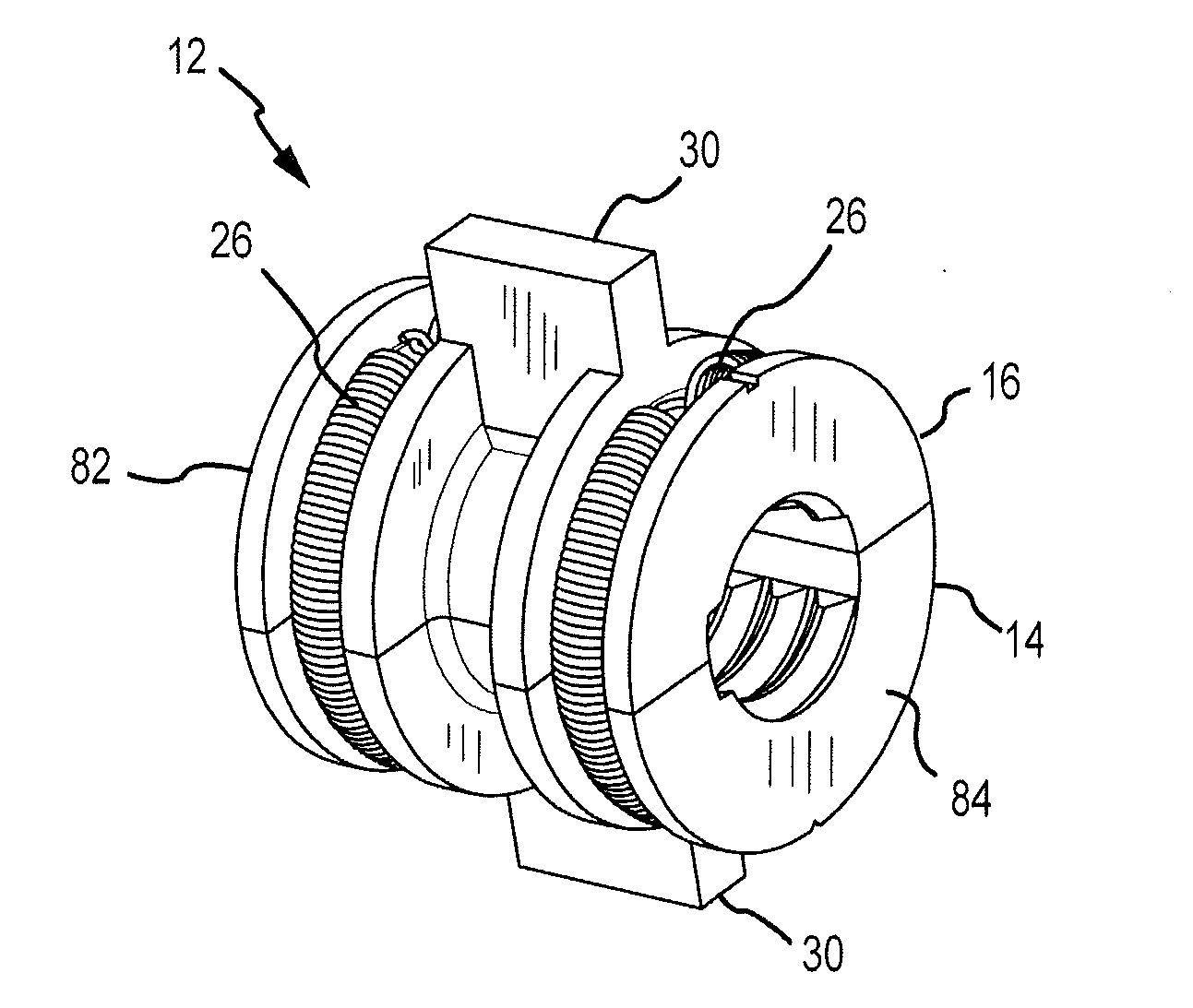
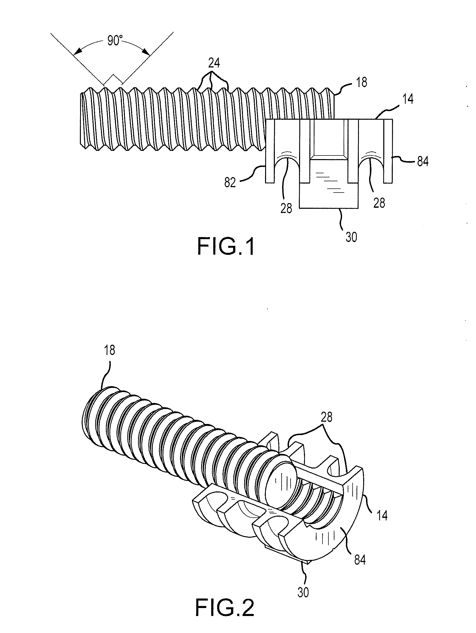
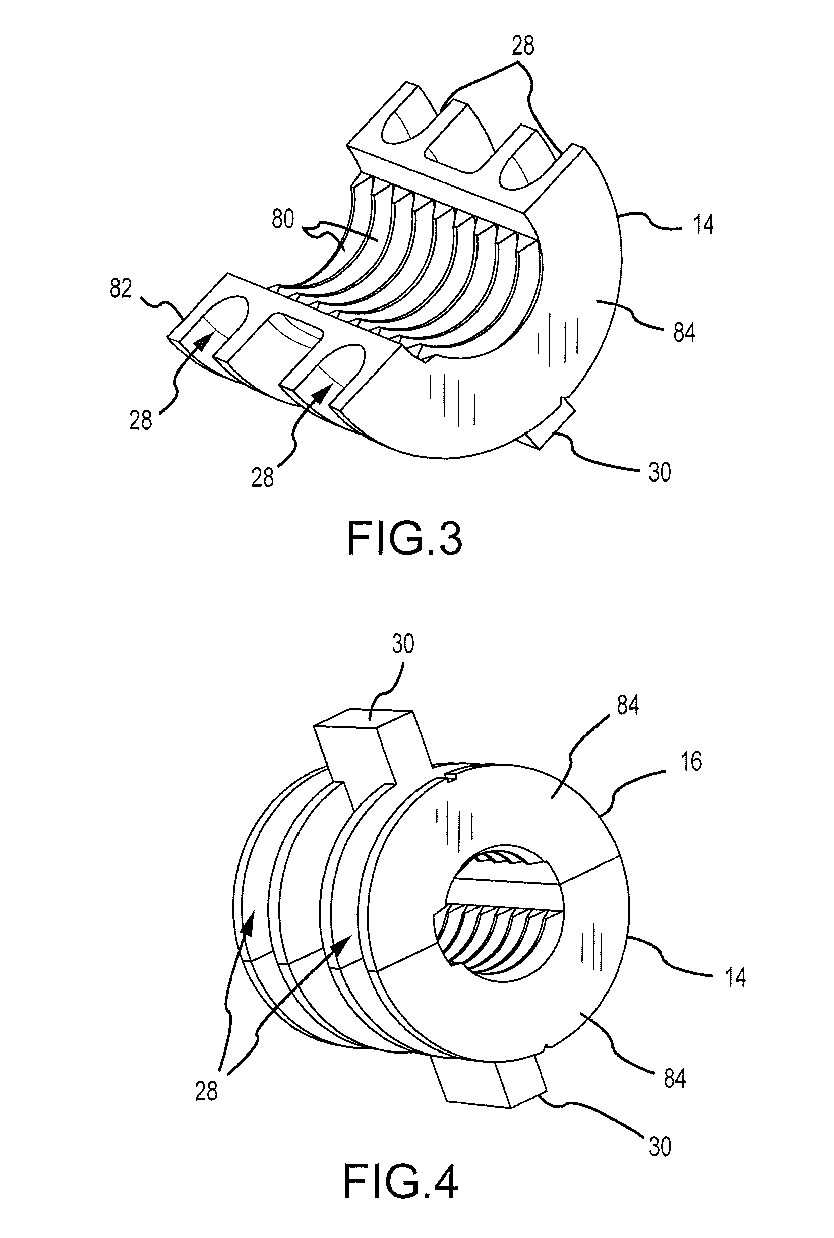
[0037]One embodiment of a motor mechanism 10 of the present invention will now be described. With reference to FIGS. 1-5 and 11, a split nut assembly 12 is shown. As illustrated, the split nut 12 comprises two half nuts 14, 16 which threadably engage and interact with a drive screw 18 mounted on the output shaft 20 of an electric motor 22. While two half nuts 14, 16 are shown in the accompanying figures, it should be appreciated that the split nut assembly be made of two or more pieces but preferably no more than four. In addition, not all of the pieces comprising the nut assembly are required to threadably interact with the threads 24 of the screw, although all of the components may threadably couple to the screw threads. Biasing members 26, such as springs or elastomeric rings, are positioned in channels 28 formed on the exterior of the half nuts to hold the half nuts in threaded engagement with the threads 24 of the screw 18. In the embodiment illustrated, each of the half nuts 1...


PUM


Abstract

In one use, a motor mechanism for an electronic lock is disclosed. In one embodiment, the motor mechanism includes a split nut that travels along a threaded screw drive. When the split nut is physically limited from further travel along the screw drive, the split nut decouples and recouples with the screw drive to reduce drag on the motor and thereby reduce motor burnout. As a result, smaller, more cost effective and efficient electric motors may be utilized together with simplified electronics.

Description

CROSS-REFERENCE TO RELATED APPLICATION[0001]This application claims the benefit of U.S. Provisional Application No. 61 / 310,644, filed Mar. 4, 2010, the entire disclosure of which is hereby incorporated herein by reference.FIELD OF THE INVENTION[0002]Electronically controlled locks for use in access control are becoming more popular. For example, an increasing number of locking systems permit users to lock and unlock a door by way of an electronic lock rather than with a traditional key. The motor mechanism described herein has application in access control environments in association with not only door locks but also in connection with other types of access control locks, as well as in situations involving linear movement of a coupling.BACKGROUND OF THE INVENTION[0003]In one embodiment of an electronic lock, an electric motor rotates a threaded driver or screw to move a follower along the screw in a direction dependent upon the rotational direction of the screw. The follower is typi...

Claims


Application Information

Patent Timeline
Patent Type & Authority Applications(United States)
IPC IPC(8): E05B47/00
CPCE05B47/00Y10T74/1974Y10T74/19735Y10T70/7051Y10T292/1021E05B2047/0023E05B47/0012E05B2047/0031E05B2047/0016F16H2025/204
Inventor WEUM, DAG TRYGVE
Owner ASSA ABLOY AB
Why Eureka
Try Eureka