Image-capturing device and in-vehicle camera

a technology of image capture device and in-vehicle camera, which is applied in the direction of color television details, closed-circuit television systems, television systems, etc., can solve the problems of inability to obtain a high-quality (clear) image, inability to perform positioning adjustment with high accuracy, and inability to obtain a bonding strength equal or more than that of the screw-fastening. achieve the effect of high accuracy

Inactive Publication Date: 2011-09-08
RICOH KK
View PDF7 Cites 52 Cited by
  • Summary
  • Abstract
  • Description
  • Claims
  • Application Information

AI Technical Summary

Benefits of technology

[0015]At least an object of the present invention is to provide an image-capturing device and an in-vehicle camera, in each of which positions of an imaging element and an imaging optical system can be strongly fixed under a state where positions of the imaging element and the imaging optical system have been adjusted with high accuracy.

Problems solved by technology

In such an imaging-capturing device, if positions of the imaging element and the imaging optical system which are positioning-adjusted with high accuracy shift, a focus position shifts and it is impossible to obtain a high-quality (clear) image.
However, anchorage strength equal to or more than that of the screw-fastening cannot be obtained by only bonding.
Moreover, in the method by only screw-fastening, because the positioning adjustment is limited by a pitch of the screw or a position of a hole, the positioning adjustment cannot be performed with high accuracy.
However, the following problems arise in the positioning adjustment described in JP H09-54233 A.
Accuracy is limited by the pitch of the screw, due to the positioning adjustment being performed with the screw.
That is to say, it is impossible to freely adjust the position of the first member which retains the optical element with a device different from that for positioning adjustment of the optical module, and an accurate adjustment higher than that of the method by bonding can not be achieved.
That is, two adjustments of positioning are necessary, which takes time to perform.
Thus, even if such a positioning adjustment described in JP H09-54233 A is applied to a positioning adjustment of the imaging element and the imaging optical system, the positions of the imaging element and the imaging optical system can not be strongly fixed under a state where the positions of the imaging element and the imaging optical system have been adjusted with high accuracy, and a stable and high-quality image cannot be obtained, due to the above-mentioned problems.

Method used


Image

  • Image-capturing device and in-vehicle camera
  • Image-capturing device and in-vehicle camera
  • Image-capturing device and in-vehicle camera

Examples


embodiment 1

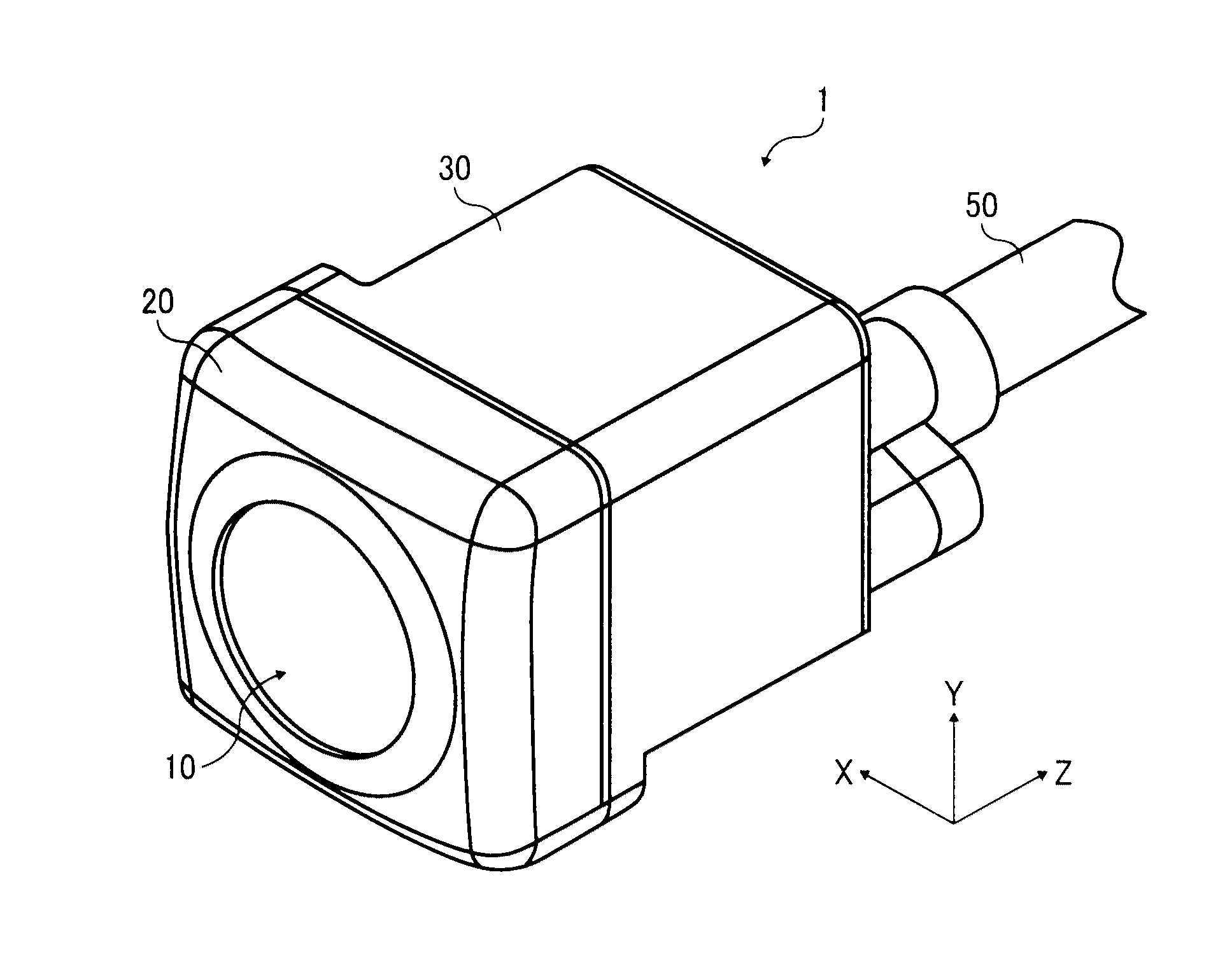
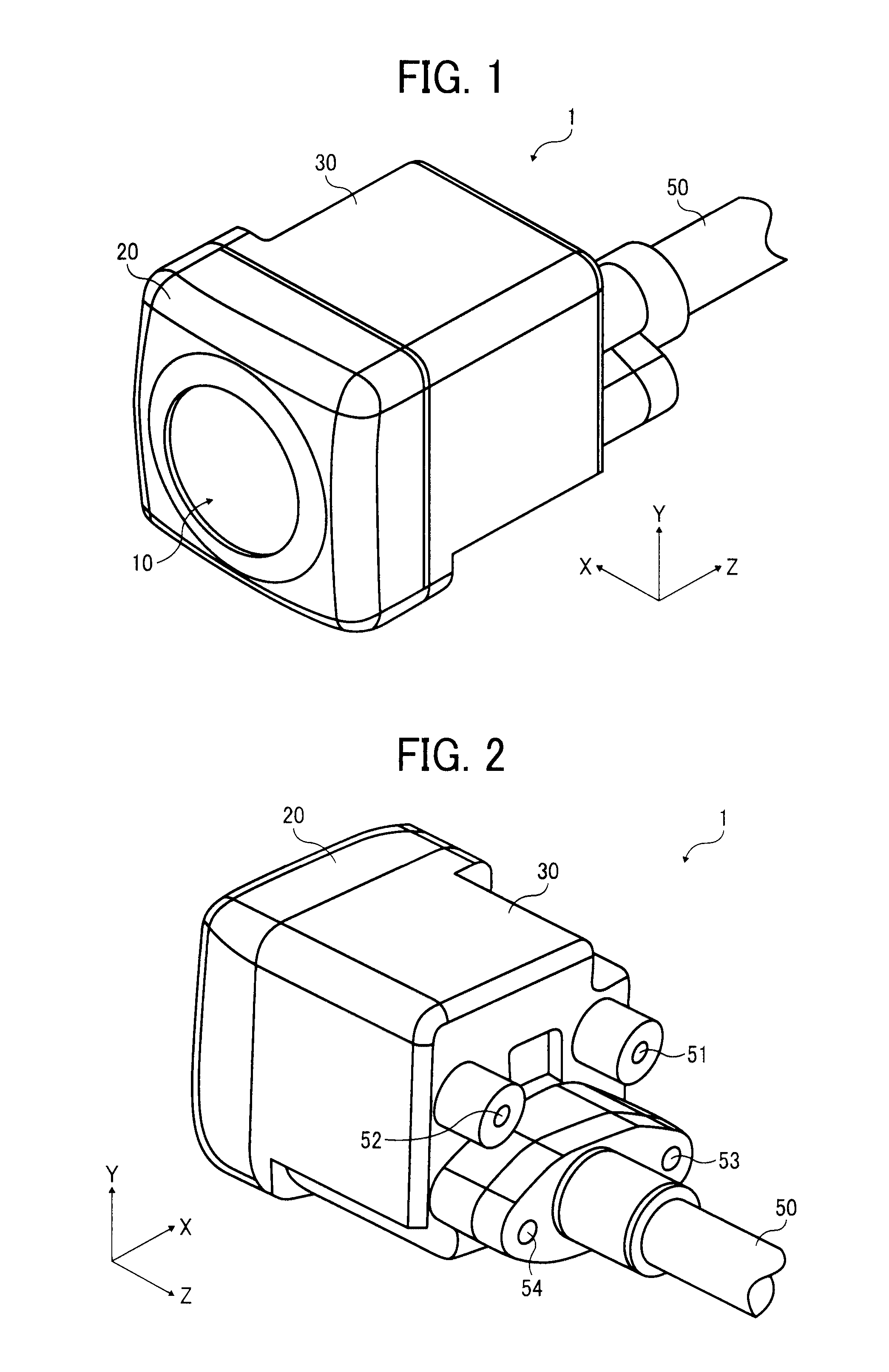
[0047]FIG. 1 is a perspective view illustrating an appearance of a front side of an image-capturing device according to an embodiment of the present invention. In addition, FIG. 2 is a perspective view illustrating an appearance of a back side of the image-capturing device. The image-capturing device in Embodiment 1 is an example of an application to a back monitor camera used as an in-vehicle camera. For example, the back monitor camera is set up around a number plate or the like at a rear section of a body of a vehicle (a car). And, a lower area on a rear side of the vehicle body is imaged (a moving image) by the back monitor camera, and is displayed on a display which is set up in a vehicle interior.

[0048]As illustrated in FIG. 1 and FIG. 2, the image-capturing device 1 (the in-vehicle camera; the back monitor camera) according to Embodiment 1 includes: an imaging lens system (an imaging optical system) 10; a lens cell 20 which is formed of a resin material and retains the imagin...

embodiment 2

[0075]Embodiment 2 is a variation on a screw fastening position when the substrate 40 is screwed and fastened to the substrate joint walls of the lens cell 20. For example, as illustrated in FIG. 9A, screw holes 25a and 25b are respectively formed in the substrate joint walls 22a and 22c where the joint intermediate members 23 are joined, and a screw hole 25c is formed in the substrate joint wall 22d.

[0076]That is, the screw hole 25c of the substrate joint wall 22d is located on a straight line B which connects middle points of the substrate joint wall 22b and the substrate joint wall 22d in a direction of the X axis, and the screw hole 25a of the substrate joint wall 22a and the screw hole 25b of the substrate joint wall 22c are arranged at symmetrical positions relative to the straight line B (positions such that a straight line connects the screw holes 25a and 25b becomes the shortest).

[0077]Moreover, as illustrated in FIG. 9B, two screw holes 25a and 25b are formed in the subst...

embodiment 3

[0080]In Embodiment 3, as illustrated in FIG. 10, on each of the tip faces of the substrate joint walls 22b and 22d of the lens cell 20 where the substrate 40 is screw fastened, at least one minute rib 60 is formed along a direction of the optical axis of the imaging lens system 10 (a direction of the Z axis). Other structures are similar to those in Embodiment 1.

[0081]The at least one rib 60 is disposed to be located near each of the screw holes 25a, 25b and 25c of the substrate joint walls 22b and 22d. For each of the substrate joint walls 22b and 22d, it is preferable that at least two ribs 60 be arranged at symmetrical positions with respect to the optical axis. The entire substrate 40 can be kept at a same height with the ribs 60. The height of each of the ribs 60 is set in such a range that the substrate can be kept at a position where a subject image is imaged by the imaging lens system 10, on the light receiving surface of the image sensor 41 within a range of a tolerance fo...


PUM


Abstract

An image-capturing device including: an imaging optical system which is configured to capture an optical image of a subject; an imaging optical system retaining member which retains the imaging optical system; an imaging element which is configured to convert the optical image into an electrical signal; a substrate which is arranged on a back side of the imaging optical system retaining member and retains the imaging element; and a plurality of substrate joint pieces each of which extends from the imaging optical system retaining member toward the substrate, wherein tip parts of the plurality of substrate joint pieces on a substrate side and the substrate are joined by an indirect bond structure using at least one joint intermediate member which is adhered to at least one of the tip parts of the plurality of substrate joint pieces and the substrate with an adhesive, and a fixation structure.

Description

CROSS-REFERENCE TO THE RELATED APPLICATION[0001]The entire contents of Japanese patent application No. JP 2010-048898, filed on Mar. 5, 2010, of which the convention priority is claimed in this application, are incorporated hereinto by reference.BACKGROUND OF THE INVENTION[0002]1. Field of the Invention[0003]The present invention relates to an image-capturing device and an in-vehicle camera.[0004]2. Description of the Related Art[0005]An image-capturing device into which an imaging optical system and an imaging element such as a CCD image sensor are built, besides being used in a digital still camera or the like, has recently been used as well in an in-vehicle camera such as a back monitor camera (a rear view camera, a rear view monitor).[0006]In such an imaging-capturing device, if positions of the imaging element and the imaging optical system which are positioning-adjusted with high accuracy shift, a focus position shifts and it is impossible to obtain a high-quality (clear) imag...

Claims


Application Information

Patent Timeline
Patent Type & Authority Applications(United States)
IPC IPC(8): H04N7/18H04N5/225
CPCH04N5/2253H04N5/2257H04N5/2254H04N23/54H04N23/57H04N23/55
Inventor TANAKA, CHIHIROTAKEMOTO, HIROSHINAKAJIMA, MITSURUKANATANI, SHINOBUSHIMIZU, KOHEISASAKI, NORIHIKO
Owner RICOH KK
Why Eureka
Try Eureka