Optical apparatus for magnifying a view of an object at a distance

Active Publication Date: 2011-09-08
SHIRASAKI MASATAKA
View PDF4 Cites 7 Cited by
  • Summary
  • Abstract
  • Description
  • Claims
  • Application Information

AI Technical Summary

Benefits of technology

[0015]The magnifier plate with or without the beam multiplier plate and/or the angle adjuster plate may be constructed as a thin plate with a thickness of a few millimeters, through which the object is viewed. Therefore, with the magnifying apparatus of the present invention, an object at a distance appears in the magnifying apparatus as a magnified image. The magnifying apparatus can be used for viewing an object at a distance in a way similar to the use of a conventional magnifier for viewing an object in a short distance. Applications of the present invention include an attachment to eyeglasses or eyeglass lens itself. This application of the

Problems solved by technology

Conventional telescopes do not provide a large view

Method used


Image

  • Optical apparatus for magnifying a view of an object at a distance
  • Optical apparatus for magnifying a view of an object at a distance
  • Optical apparatus for magnifying a view of an object at a distance

Examples


Example

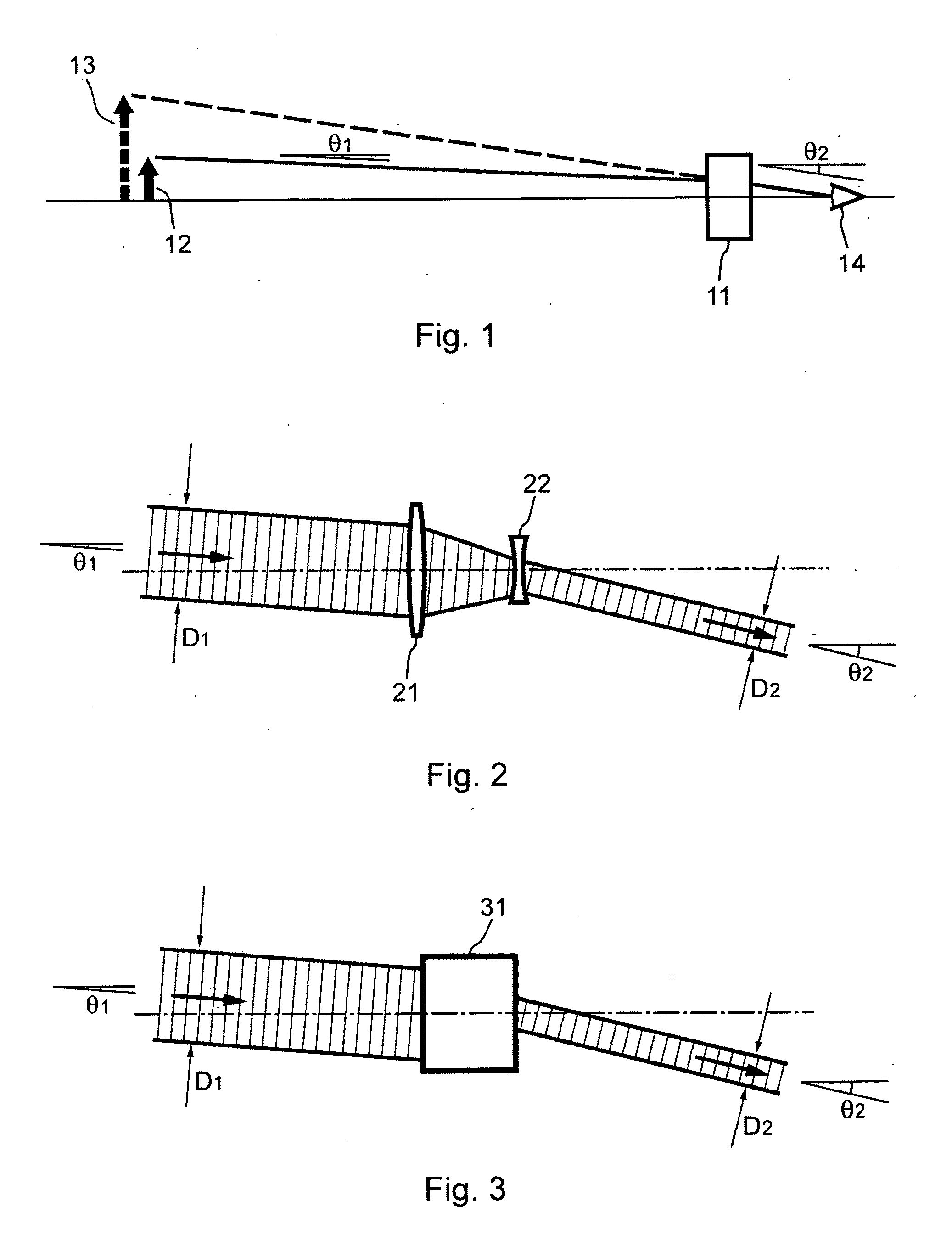
[0075]A magnifying apparatus such as a telescope works as shown in FIG. 1. A ray with a traveling angle θ1 coming from an object 12 whose distance is virtually at infinity is converted through a magnifying apparatus 11 such as a telescope into a ray with a larger traveling angle θ2, where both traveling angles are defined as angles with respect to the axis of the magnifying apparatus. The eye 14 sees the ray with angle θ2, and therefore, sees the image 13 of the object in the direction at angle θ2. Assuming θ2 is in proportion to θ1, the image of the object is magnified and the magnification is given by the ratio θ2 / θ1.

[0076]A well known design of Galileo telescope consists of a convex lens and a concave lens, and has the function of enhancing of the traveling angle described in FIG. 1. If a Galileo telescope is designed to make a view area to be, for example, a centimeter in diameter, the total length of the telescope will be several times longer than the diameter, that is, several...


PUM


Abstract

Described are new magnifying apparatus based on two dimensional arrays of micro magnifying modules (MMMs) positioned along a plane perpendicular to the axis of the magnifying apparatus. In addition, the structure may include a two dimensional array of micro beam multipliers (MBMs) to improve the quality of the magnified image. The micro beam multipliers are positioned along a plane parallel to the array of micro magnifying modules. The structure also may include a two dimensional array of ray angle adjusters (RAAs) to extend the view angle. The ray angle adjusters are positioned along a plane parallel to the array of micro magnifying modules. The array of micro magnifying modules, with or without the micro beam multipliers and/or ray angle adjusters, may be constructed as a thin plate with a thickness of a few millimeters, through which the object is viewed. An object at a distance appears in the magnifying apparatus as a magnified image and the magnifying apparatus can be used for viewing an object at a distance in a way similar to the use of a conventional magnifier for viewing an object in a short distance.

Description

RELATED APPLICATIONS[0001]This application is a continuation-in-part application of application Ser. No. 12 / 798,358, filed Apr. 2, 2010.[0002]This application claims the benefit of provisional Application No. 61 / 339,305, filed Mar. 3, 2010, which application is incorporated herein by reference.[0003]This application also claims the benefit of provisional Application No. 61 / 343,936, filed May 6, 2010, which application is incorporated herein by reference.[0004]This application also claims the benefit of provisional Application No. 61 / 403,075, filed Sep. 10, 2010, which application is incorporated herein by reference.BACKGROUND OF THE INVENTION[0005]The present invention relates to optical magnifying devices for magnifying a view of an object at a distance.[0006]To magnify a view of an object or scene at a distance, the most common apparatus is a telescope. A well known telescope design is a Galileo telescope, which consists of a convex lens and a concave lens. The fundamental functio...

Claims


Application Information

Patent Timeline
IPC IPC(8): G02B17/08G02B17/06G02B27/10G02B27/14
CPCG02B17/002G02B17/0808G02B17/0812G02C7/08G02B25/007G02B27/10G02B17/086
Inventor SHIRASAKI, MASATAKA
Owner SHIRASAKI MASATAKA
Why Eureka
Try Eureka