Image forming apparatus

a technology of image forming apparatus and forming apparatus, which is applied in the direction of electrographic process apparatus, instruments, optics, etc., can solve the problems of deterioration of developers, low image density, and lowering of developing property

Inactive Publication Date: 2011-09-08
CANON KK
View PDF7 Cites 6 Cited by
  • Summary
  • Abstract
  • Description
  • Claims
  • Application Information

AI Technical Summary

Benefits of technology

[0013]A principal object of the present invention is to provide an image forming apparatus in which image density lowering on an image after fixation is less liable to occur even in the case where an amount of a developer for a solid image to be transferred onto a sheet material is decreased with operation (use) of a process cartridge.

Problems solved by technology

However, the above-described conventional image forming apparatus involves the following problems.
When the lower in developing property expensively proceeds particularly with respect to a solid image, an image density becomes low.
For this reason, when the operation amount of the process cartridge is increased, the developer in the developing device is repetitively subjected to rubbing, stirring and circulation by this developing blade, so that the developer is deteriorated.
When the developer is deteriorated in such a manner, compared with a fresh developer, behavior such as a charging property or flowability is changed, thus causing the lowering in developing property.
Thus, when the developer carrying member surface is smoothed, it is difficult to carry a sufficient amount of the developer on the developer carrying member surface, so that the lowering in developing property is invited.
However, even in the case where these conventional techniques are used, when the operation amount of the process cartridge is increased, the “lowering in developing property” occurs and then an image decreased in density is formed in some cases.
Particularly, in the case of a constitution in which the developer on the developer carrying member is formed in a thin layer and has high triboelectric charge and in which a sharp image is formed by bringing a developing efficiency of a solid image near to 100%, the techniques disclosed in JP-A Hei 7-160109, JP-A 2003-307994 and U.S. Pat. No. 6,917,772 are inadequate.
Incidentally, in this case, attention is paid to unevenness (projection and recess) of the sheet material P at the protruded printer of the fiber but the “texture exposure due to fixation” is also caused by slight non-uniformity of a heat conductivity characteristic of the sheet material P or the rotatable member.
Further, in some cases, the “texture exposure due to fixation” is caused also by slight non-uniformity of the toner amount on the sheet material P or non-uniformity of the amount of heat per unit toner amount.

Method used


Image

  • Image forming apparatus
  • Image forming apparatus
  • Image forming apparatus

Examples


embodiment 1

(1: Image Forming Apparatus)

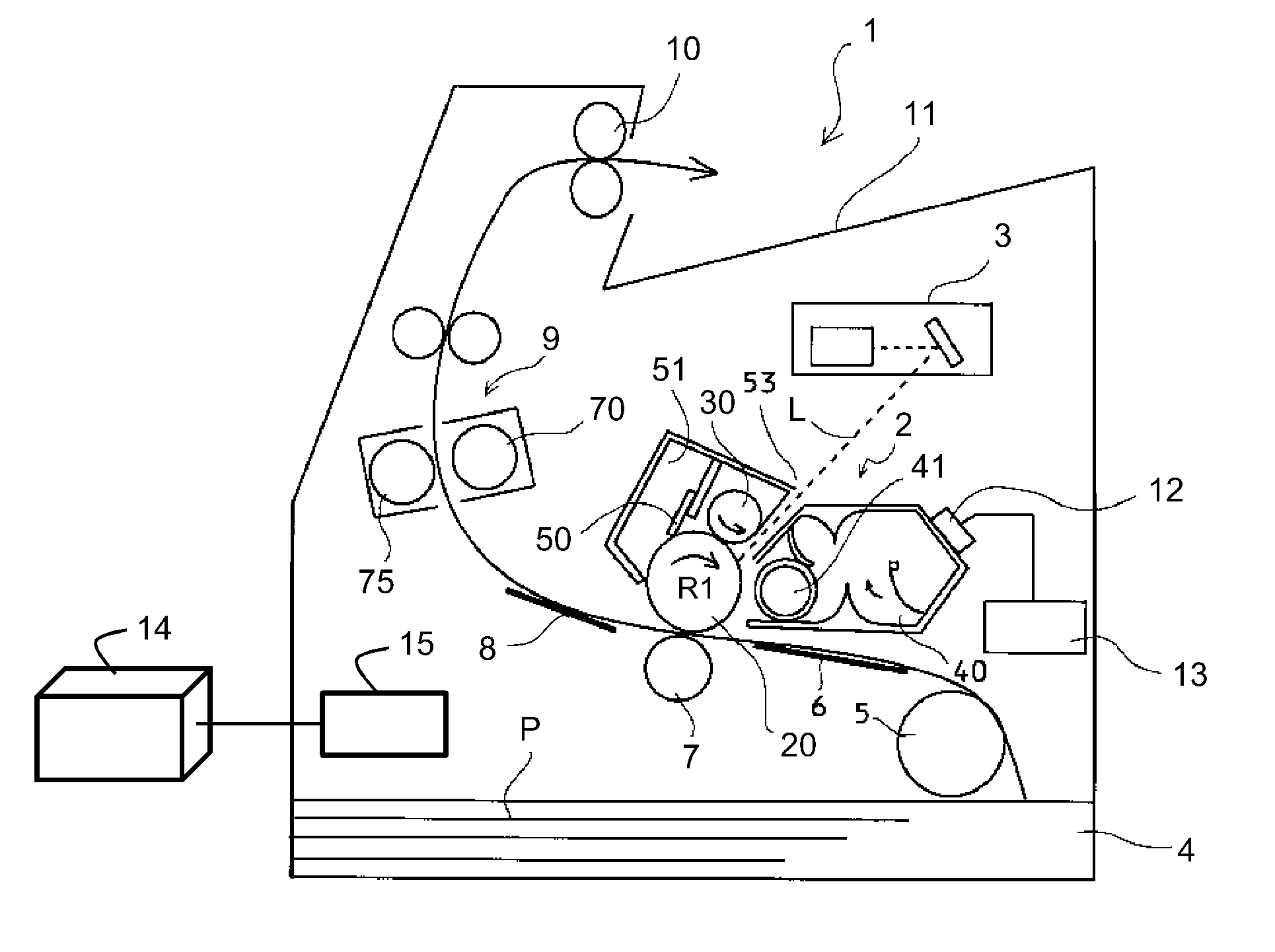
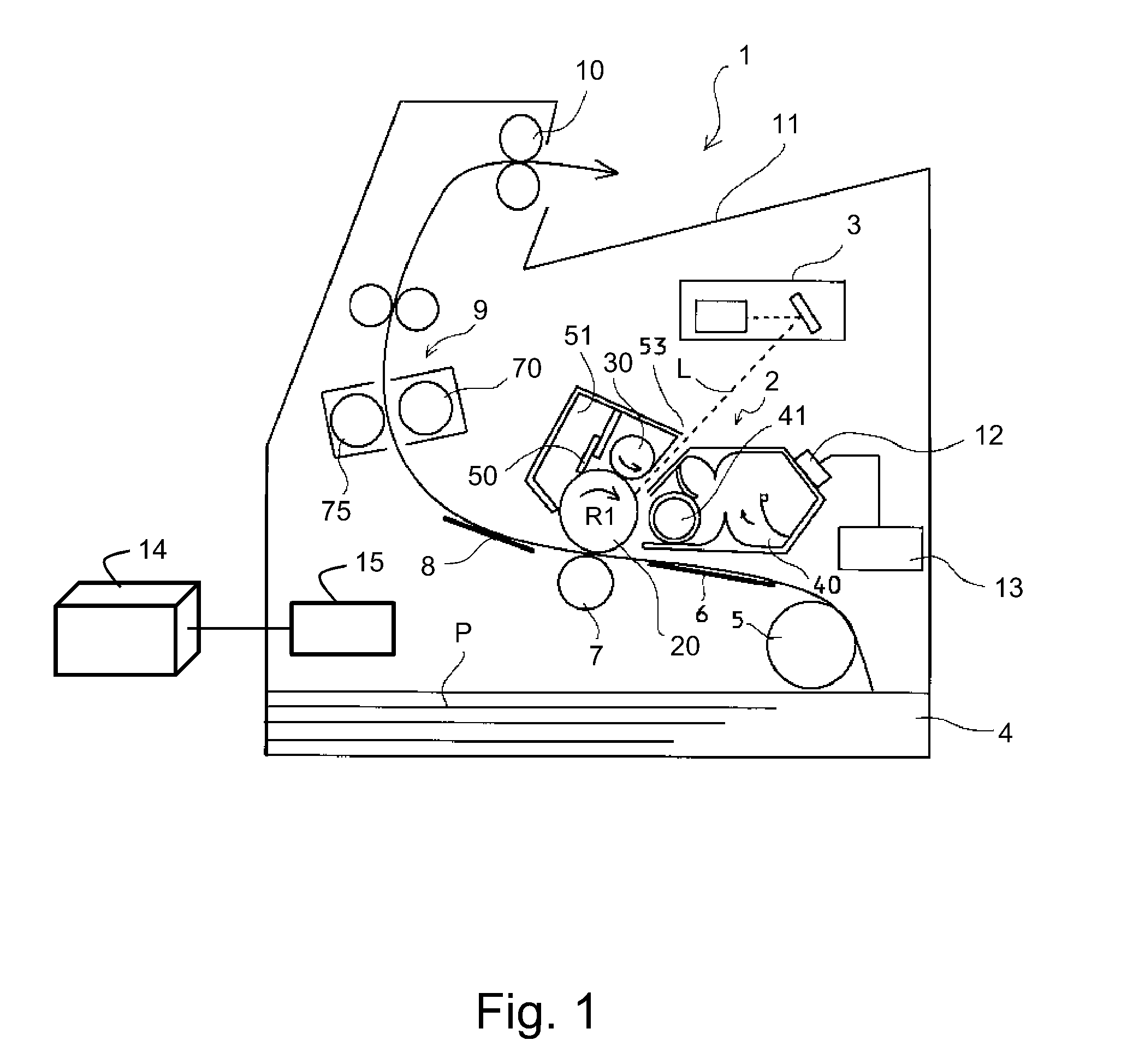
[0028]With reference to FIG. 1, the image forming apparatus according to this embodiment of the present invention will be described. The image forming apparatus in this embodiment is a laser beam printer of an electrophotographic type and a process cartridge mounting and demounting type.

[0029]To a printer 1 in this embodiment, an external host device 14 such as a personal computer or an image reading device (image scanner) is connectable. By such a constitution, image information is inputted from the external host device 14 into a controller (control portion) 15. On the basis of the inputted image information, the controller 15 drive-controls respective members and devices of the image forming apparatus.

[0030]The printer 1 includes a process cartridge 2 detachably mountable to a printer main assembly (main assembly of the image forming apparatus). Incidentally, herein, the “printer main assembly (apparatus main assembly)” refers to a constitution in which...

second embodiment

[0068]This embodiment is characterized in that a parameter obtained by weighting of the index indicating the operation environment in which the image formation was effected is used. Incidentally, the constitution of the image forming apparatus is identical to that in First Embodiment described above, thus being omitted from the description.

[0069]It has been understood that the deterioration of the developing device is accelerated particularly in a high temperature and high humidity environment. On the other hand, according to study by the present inventors, it has been understood that a speed of the deterioration is not largely affected by an operation environment in a low temperature and low humidity environment or in a normal temperature and normal humidity environment.

[0070]Therefore, in this embodiment, in the case where the high temperature and high humidity environment is detected by an unshown temperature and humidity sensor (environment detecting means), weighting (correctio...

third embodiment

[0081]In Second Embodiment described above, the constitution in which the operation environment was measured by using the temperature and humidity sensor was described. This embodiment is characterized in that the operation environment (temperature, humidity) is determined on the basis of a resistance value of the transfer roller 7.

[0082]A technique using a control method of ATVC type for controlling a transfer voltage Vt to be applied to the transfer roller has been conventionally known. In this control method, a predetermined current I is applied during the image formation, and from a detected voltage value Vo at that time, a resistance R of the transfer roller is detected and then a transfer voltage Vt depending on the resistance R is determined. Therefore, in this embodiment, environment detection is effected by using the phenomenon that the resistance value R of the transfer roller is lowered in the high temperature and high humidity environment.

[0083]In this embodiment, the pr...


PUM


Abstract

An image forming apparatus includes an image bearing member for bearing a developer image; a developing device including a developer carrying member for forming the developer image on the image bearing member; a fixing device for fixing the developer image on a sheet material, on which the developer image has been transferred, by heating the sheet material; a memory medium for storing an operation hysteresis value, of the developing device, which varies depending on a state of an operation of the developing device from start of the operation; and a controller for controlling a temperature of the fixing device. The controller controls, when the operation hysteresis value stored in the memory medium reaches a preset threshold, the temperature of the fixing device so as to be lower than that before the operation hysteresis value reaches the preset threshold.

Description

FIELD OF THE INVENTION AND RELATED ART[0001]The present invention relates to an image forming apparatus.[0002]As the image forming apparatus, there is an image forming apparatus of, e.g., an electrophotographic type. In the image forming apparatus of the electrophotographic type, a developing device for developing an electrostatic latent image into a developer image by supplying a developer to the electrostatic latent image formed on a surface of an image bearing member by scanning exposure is provided. The developing device includes a developer carrying member for carrying the developer, a developer container for controlling the developer, and the like and is constituted so that the developer carried on the surface of the developer carrying member is supplied electrostatically to the surface of the image bearing member. Incidentally, in recent years, the developing device is integrally assembled into a process cartridge together with the image bearing member and another process mea...

Claims


Application Information

Patent Timeline
Patent Type & Authority Applications(United States)
IPC IPC(8): G03G15/00G03G15/20
CPCG03G15/20G03G15/00
Inventor KATO, MASAHITONAITO, NORIHITOMATSUNAGA, TOMONORIIKEDA, TAKAHIRO
Owner CANON KK
Why Eureka
Try Eureka