
Displacement detection apparatus and method of correcting error of scale used for displacement detection apparatus

a displacement detection and scale technology, applied in the field of displacement detection apparatuses, can solve the problems of enlarged amount of mark pitch error, inability to maintain linearity of scale, and difficulty in improving the accumulated position accuracy of encoders, so as to reduce the accumulated position error of scales

Inactive Publication Date: 2011-09-08
CANON KK
View PDF4 Cites 42 Cited by
  • Summary
  • Abstract
  • Description
  • Claims
  • Application Information

AI Technical Summary

Benefits of technology

The present invention provides a displacement detection apparatus and an error correction method that can reduce the accumulated position error of a scale used for the apparatus. The apparatus includes a scale with multiple marks, two sensors that detect the positions of the marks, and a processor that calculates a correction value for the distance between the marks based on the distance between the sensors, the time required for the marks to pass by the sensors, and the movement of the sensors. This correction value is then used to adjust the position of the scale and improve the accuracy of the displacement detection.

Problems solved by technology

However, even if the size error of the mark pitch is reduced, a scale recording the marks may be obliquely mounted on the apparatus and also the mark pitch may be expanded or contracted due to the mechanical stress or the temperature change in fixing and mounting the scale.
Therefore, it is difficult to improve an accumulated position accuracy of the encoder.
In particular, when the scale is made of an inexpensive thin-film material, the linearity of the scale cannot be maintained and an amount of the mark pitch error is enlarged.

Method used


Image

  • Displacement detection apparatus and method of correcting error of scale used for displacement detection apparatus
  • Displacement detection apparatus and method of correcting error of scale used for displacement detection apparatus
  • Displacement detection apparatus and method of correcting error of scale used for displacement detection apparatus

Examples


Embodiment Construction

[0022]Exemplary embodiments of the present invention will be described below with reference to the accompanied drawings. In each of the drawings, the same elements will be denoted by the same reference numerals and the duplicate descriptions thereof will be omitted.

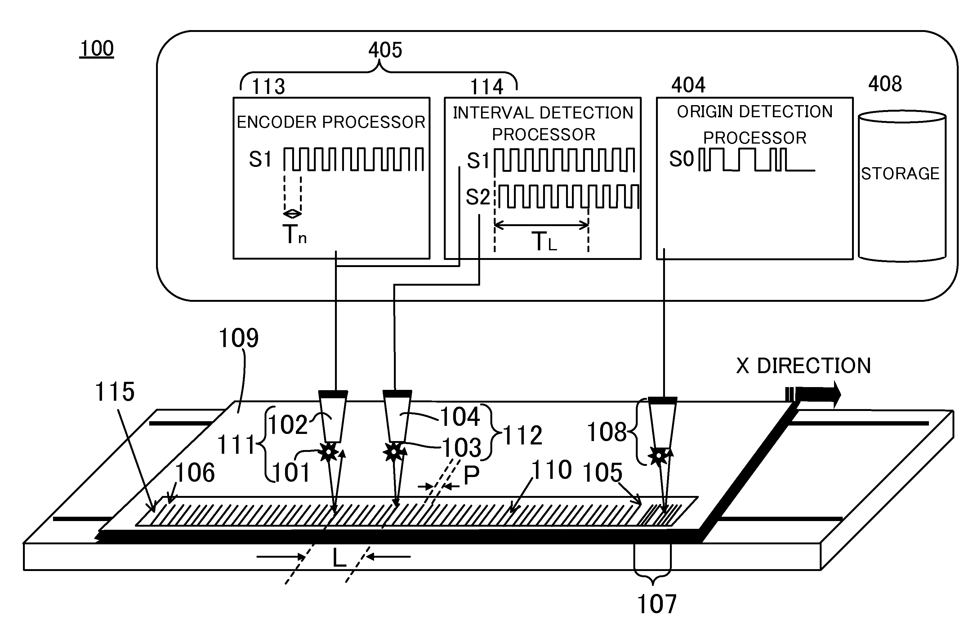
[0023]First of all, an outline of a displacement detection apparatus in the embodiment of the present invention will be described. The displacement detection apparatus in the present embodiment is configured to be able to perform a method of correcting an error of a scale used for the displacement detection apparatus in which a plurality of marks are periodically disposed. FIG. 1 is a schematic configuration diagram of a linear displacement detection apparatus 100 in the present embodiment. In the present embodiment, all of a first position detection sensor 111, a second position detection sensor 112, and an origin detection sensor 108 are optical reflection sensors. The first position detection sensor 111 and the second ...


PUM


Abstract

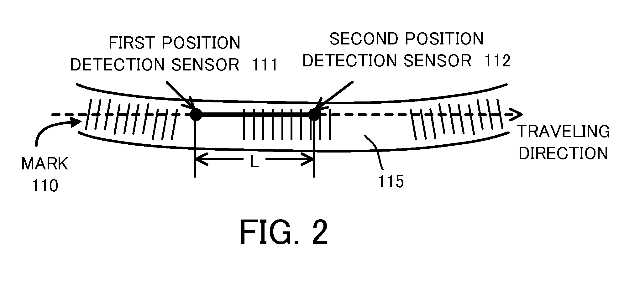
A displacement detection apparatus includes a scale 115 on which marks are disposed, first and second position detection sensors 111 and 112 detecting positions of the marks 110, and a processor 409 performing a calculation processing of an output signal from each of the first and second position detection sensors 111 and 112. The first and second position detection sensors 111 and 112 are disposed at a distance L from each other to be movable relative to the scale 115. The processor 409 calculates a correction value P′ of a mark pitch P of the marks 110 using the distance L, a first time TPK required for K marks of the marks 110 to pass a detection position, and a second time TL required for a specific mark of the marks 110, which are measured at the same time of the first time TPK, to move the distance L.

Description

CROSS REFERENCE TO RELATED APPLICATION[0001]This is a continuation of International Application PCT / JP2011 / 000249, having an international filing date of 19 Jan. 2011, which claims priority to JP 2010-009828, filed 20 Jan. 2010 and JP 2011-008424, filed 19 Jan. 2011. The disclosures of the PCT application and the priority application, in their entity, including the drawings, claims, and the specifications thereof, are incorporated herein by reference.BACKGROUND OF THE INVENTION[0002]1. Field of the Invention[0003]The present invention relates to a displacement detection apparatus that reduces an accumulated position error of a scale used for the displacement detection apparatus.[0004]2. Description of the Related Art[0005]An encoder (a displacement detection apparatus) is a device that reads periodic marks contained previously to calculate a relative displacement amount based on a product of a mark pitch and the number of the mark pitches. Because the accuracy of the mark pitch is c...

Claims


Application Information

Patent Timeline
Patent Type & Authority Applications(United States)
IPC IPC(8): G06F15/00
CPCG01P3/64G01D5/245G01D5/244G01D5/12G01D5/24476G01D5/34746
Inventor TAKAHAMA, SHINICHIROIGAKI, MASAHIKOMIYAOKA, YASUYUKIARIMITSU, YASUMICHI
Owner CANON KK
Learn More