Method, apparatus and trace module for generating timestamps

a timetamp and trace module technology, applied in the field of data processing, can solve the problems of increasing the amount of trace data in the trace stream, wasting trace bandwidth, and wasting trace buffer capacity and trace port bandwidth, and achieve the effect of saving trace bandwidth and fewer trace packets

Active Publication Date: 2011-09-08
ARM LTD
View PDF11 Cites 47 Cited by
  • Summary
  • Abstract
  • Description
  • Claims
  • Application Information

AI Technical Summary

Benefits of technology

[0009]In the present technique, trace packets indicative of at least one characteristic of a data processing apparatus or data processing performed by the apparatus are generated. When a predetermined event occurs, a procedure for generating a timestamp is triggered. However, the present technique recognises that it is not desirable to generate the timestamp immediately on the occurrence of a predetermined event. Instead, when the predetermined event occurs, a timestamp request flag is set, indicating that a timestamp request is pending. Then, upon generation of a following trace packet, the timestamp request flag is checked to see whether a timestamp request is pending, and when the timestamp request flag indicates that a timestamp request is pending, a timestamp corresponding to the following trace packet is generated, and the timestamp request flag is then set to indicate that no timestamp request is pending. This technique forces the timestamp to be generated at a point where a new trace packet is also generated. This means that the timestamp can be output with the generated following trace packet, thus avoiding a timestamp packet being inserted into the trace stream when no trace data has been generated. By avoiding the generation of packets that only contain a timestamp and do not contain any trace data, the trace stream contains fewer trace packets and so the trace bandwidth of, for example, a trace buffer or a trace output port, is used more efficiently. Also, the present technique means that, if no more trace packets are output for a particular trace stream (for example, if the processing being monitored has been completed), then no timestamp is inserted into the stream during that time and so trace resources are conserved.
[0020]A trace module for generating trace information indicating the operation of a processor need not be enabled all the time. When, for example, data processing whose operation is well known is being performed, or when it is desired to save on trace bandwidth, then the trace module can be disabled to save trace resources. Therefore the trace module may have logic for enabling or disabling generation of trace packets. The present technique recognises that if generation of trace packets is disabled and then later re-enabled during data processing, it is possible that a trace stream may be monitoring a different process following re-enablement of the generation of trace packets than before the generation of trace packets was disabled. In this case, it is useful to include a timestamp following re-enabling of the generation of trace packets. Therefore, while the generation of trace packets is disabled, the present technique continues to monitor whether or not the at least one predetermined event has occurred, and if such an event has occurred, then the timestamp request flag is set to indicate a pending timestamp request, independently of whether the generation of trace packets is enabled or disabled. When a following trace packet is generated after re-enabling the generation of trace packets, then if the timestamp request flag indicates that a timestamp request is pending, the timestamp is generated. This enables reconstruction of the order of generation of trace packets that were generated before and after the disabling of generation of trace packets.
[0025]Some systems having trace capability may operate with more than one timing scheme. For example, local trace sources, such as an embedded trace macrocell (ETM) or instrumentation trace macrocell (ITM) that are provided within a single processor cluster, may operate in accordance with a local time generator, while an external timing scheme may also be used. In such cases, it is useful to provide for correlation between the two or more different timing schemes. The present technique can be applied to such systems by applying the generated timestamp to a timestamp correlation trace packet for correlating timestamp values of a first timing scheme with timestamp values of a second timing scheme. Thus, if the timestamp request flag is set when the following trace packet is generated, the correlation trace packet is inserted into the trace stream as well as the following trace packet. The correlation trace packet can then be analysed to provide correlation between the different timing schemes. The present technique of delaying generation of the correlation packet until generation of the following trace packet is useful because it means that if the following trace packet is never generated (i.e. trace packet generation has stopped), then the correlation packet is not output, thus saving trace bandwidth.
[0026]Alternatively, or as well as the use of the correlation trace packet, the timestamp may be a time value appended to the following trace packet. For example, the time value may be added to a header of the following trace packet. This form of timestamp avoids the generation of an extra trace packet dedicated to recording a timestamp and so results in fewer trace packets being generated.
[0037]It may be desirable on some occasions to postpone the generation of the timestamp until two or more following trace packets have been generated. For example, in some situations a group of trace packets may be generated in relation to a single operation. Sometimes, when the predetermined event occurs, such a group of trace packets may be being generated relating to a previous operation, and trace packets relating to the first operation that occurs after the event may be of more interest than the group of trace packets relating to the previous operation. Therefore, the timestamp can be generated at the first trace packet that is not part of the group of trace packets relating to the previous operation. For example, if a first operation corresponds to a first group of trace packets (“1p”, “1 q”, “1 r” and “1 s”, say) and a second operation relates to a second group of trace packets (“2p”, “2q”, “2r” and “2s”, say), then generation of a timestamp corresponding to an event occurring during the first operation could be delayed until the first trace packet (“2p”) is generated after the first operation has completed. If the generation times of some types of packets (e.g. the “q”, “r” or “s” packets) are not of interest, then it can be useful to conserve trace bandwidth (and avoid risking overflow of trace resources) by postponing generation of the timestamp until the next trace packet whose timing is of interest (e.g. the next “p” packet) is generated.

Problems solved by technology

However, such timestamps use up trace bandwidth since they increase the amount of trace data in the trace stream.
If cycle-accurate trace is enabled, then fewer timestamps can be generated, but in this case then more trace data is needed so again this can be expensive in terms of trace buffer capacity and trace port bandwidth.
On the other hand, too few timestamps can prevent the order of generation of trace packets from being deduced from the trace streams.

Method used


Image

  • Method, apparatus and trace module for generating timestamps
  • Method, apparatus and trace module for generating timestamps
  • Method, apparatus and trace module for generating timestamps

Examples


Embodiment Construction

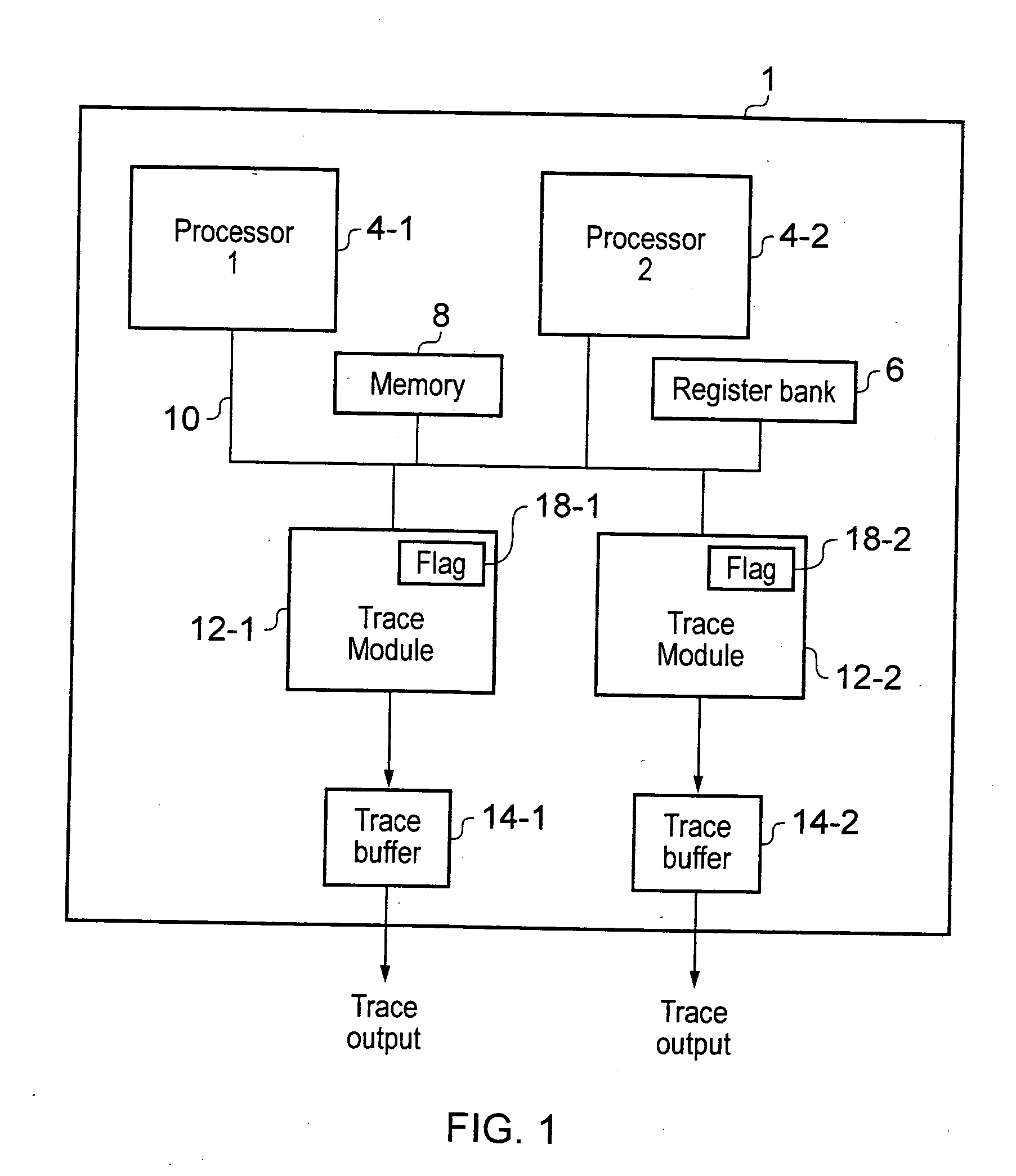
[0063]FIG. 1 schematically illustrates a data processing apparatus 1. The data processing apparatus 1 comprises processing circuitry including at least one processor 4. In the example of FIG. 1, there are two processors: a first processor 4-1, and a second processor 4-2. In the following description, where a processor is referred to generally and it is not important which particular processor is being referred to, the reference numeral 4 will be used to represent the processor. It will be appreciated that the processing circuitry may also include other processing components such as hardware accelerators, co-processors or graphics processing units, for example.

[0064]The data processing apparatus 1 also comprises a register bank 6 for storing values used during processing and a memory 8 for storing data and instructions for use by the processor 4. The processor 4, the register bank 6 and the memory 8 are connected via a bus 10.

[0065]The processing apparatus 1 also comprises at least o...


PUM


Abstract

The present invention relates to the field of data processing, in particular, a method, apparatus 1 and trace module 12 for generating timestamps while tracing characteristics of a data processing apparatus or processing being performed by the data processing apparatus. When a predetermined event occurs, a timestamp request flag 18 is set to indicate that a timestamp request is pending. Upon generation of a following trace packet, it is determined whether the timestamp request flag indicates that a timestamp request is pending, and if a request is pending then a timestamp is generated corresponding to the following trace packet, and the timestamp request flag is set to indicate that there is no pending timestamp request.

Description

FIELD OF THE INVENTION[0001]The present invention relates to the field of data processing. In particular, the invention relates to the generation of timestamps while tracing characteristics of data processing.BACKGROUND TO THE INVENTION[0002]Trace modules for generating trace information indicating characteristics of processing performed by a processing apparatus are known. It is possible to generate timestamps indicating the time of generation of trace packets and to insert the timestamps into the trace stream periodically. However, such timestamps use up trace bandwidth since they increase the amount of trace data in the trace stream. If cycle-accurate trace is enabled, then fewer timestamps can be generated, but in this case then more trace data is needed so again this can be expensive in terms of trace buffer capacity and trace port bandwidth. On the other hand, too few timestamps can prevent the order of generation of trace packets from being deduced from the trace streams. The...

Claims


Application Information

Patent Timeline
Patent Type & Authority Applications(United States)
IPC IPC(8): G06F9/44
CPCG06F11/3466G06F2201/835G06F11/348G06F11/3636
Inventor WILLIAMS, MICHAEL JOHNHALLMAN, JOHN MICHAELASHFIELD, EDMOND JOHN SIMON
Owner ARM LTD
Why Eureka
Try Eureka