Vacuum cleaner arrangement

a vacuum cleaner and cleaner body technology, applied in the field of vacuum cleaners, can solve the problems of unstable stick-vac cleaner as a whole, relatively dirty lower end of the cleaner will consequently rest against the wall, and not particularly convenient to store in stick-vac mode, so as to reduce the footprint of the docking station and facilitate the effect of cleaning

Active Publication Date: 2011-09-15
DYSON TECH LTD
View PDF32 Cites 69 Cited by
  • Summary
  • Abstract
  • Description
  • Claims
  • Application Information

AI Technical Summary

Benefits of technology

[0026]The clamping members may be arranged for relative sliding movement along a clamp axis to engage the stick-vac, with at least one clamping member additionally arranged for movement into and out of clamping alignment with the other clamping member. The ability to take a clamping member out of clamping alignment with the other clamping member allows for sequential engagement of the cleaner with the clamping members, which makes docking more convenient. The movement of the clamping member into and out of clamping alignment may be a pivoting movement. In particular, in use with the docking station mounted on a wall, said pivotable clamping member may be arranged such that, when the docking station is in use mounted on a wall, the clamping member is arranged for pivoting movement away from the wall. This latter arrangement is considered particularly advantageous in reducing the footprint of the docking station on the wall, because the pivotable clamping member moves within the footprint of the docking station.

Problems solved by technology

However, this is not an essential feature of these types of stick-vac cleaners and it is conceivable that the wand may be permanently attached to the handheld suction unit.
The “top heavy” distribution of weight in stick-vacs of the second type means that they are not particularly convenient to store in stick-vac mode.
If the stick-vac cleaner is leaned against a wall in an upright position with the floor tool supported on the floor and the handheld suction unit resting against the wall, the relative weight of the handheld suction unit tends to make the stick-vac cleaner as a whole unstable.
On the other hand, if the stick-vac cleaner is turned upside down and leaned against the wall with the relatively heavy handheld vacuum cleaner supported on the floor, the relatively dirty lower end of the cleaner will consequently rest against the wall, which is undesirable.

Method used


Image

  • Vacuum cleaner arrangement
  • Vacuum cleaner arrangement
  • Vacuum cleaner arrangement

Examples


Embodiment Construction

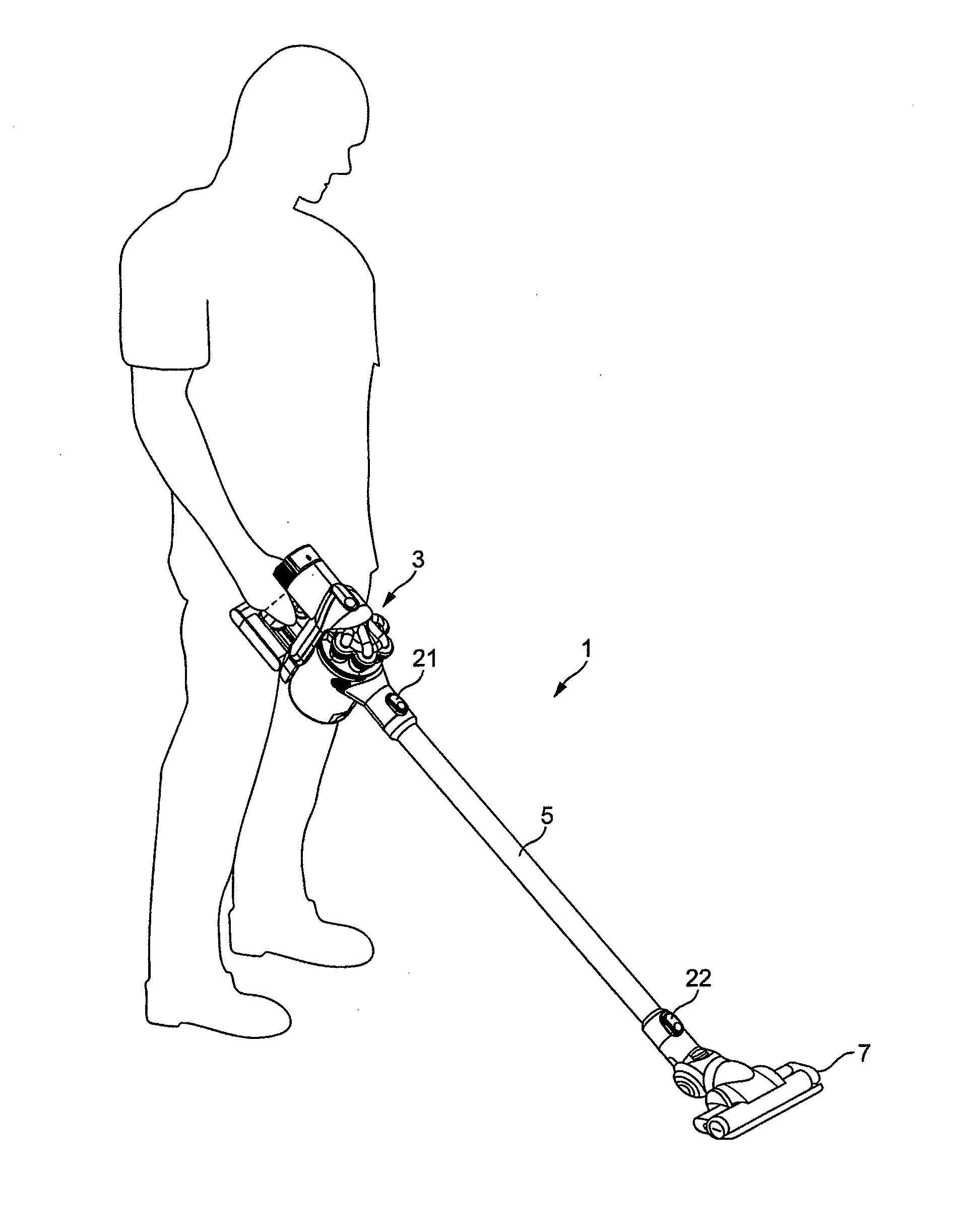
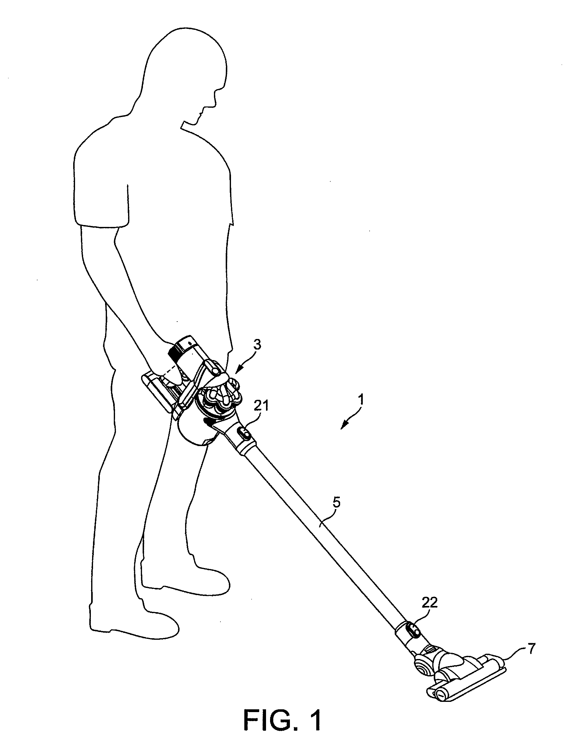
[0043]FIG. 1 shows a stick-vac cleaner 1 comprising a hand held suction unit, in the form of a handheld vacuum cleaner 3, an elongate wand 5 and a floor tool 7.

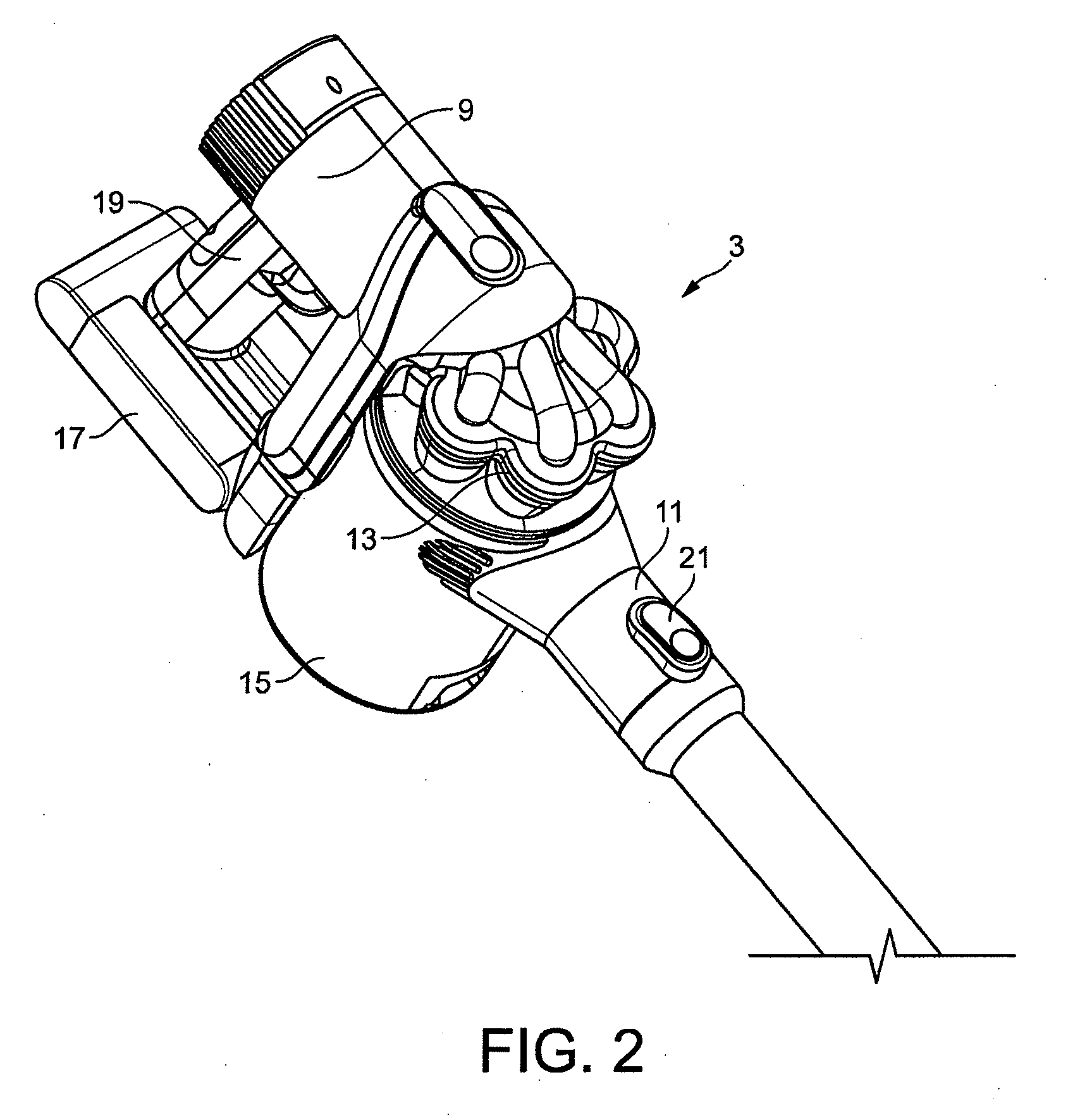
[0044]Referring to FIG. 2, the handheld vacuum cleaner 3 comprises a motor-driven fan which is arranged inside a motor casing 9 for drawing air in through a suction nozzle 11 positioned at the front of the hand held vacuum cleaner 3. Dirty air drawn in through the suction nozzle 11 is ducted under the fan-generated suction pressure through a cyclonic separation system 13, where dirt is separated from the air, before the relatively clean air is then exhausted back to atmosphere via one or more fine-particulate filters (not visible). The dirt which is separated from the airflow inside the cyclonic separating system 13 is collected in a bin 15 for disposal. The hand held vacuum cleaner 3 is powered by a multi-cell rechargeable battery which is housed in a battery pack 17.

[0045]In use, the handheld vacuum cleaner 3 is carried in ...


PUM


Abstract

An arrangement including: a handheld suction unit in combination with an elongate suction wand to form a stick-vac cleaner, the arrangement further including a wall-mountable docking station for supporting the stick-vac cleaner on a wall in an upright, docked position when not in use. The arrangement provides for relatively stable storage of the stick-vac cleaner in the upright position, convenient for use.

Description

REFERENCE TO RELATED APPLICATIONS[0001]This application claims the priority of United Kingdom Application No. 1004149.9, filed 12 Mar. 2010, and of United Kingdom Application No. 1014423.6, filed 31 Aug. 2010, the entire contents each of which are incorporated herein by reference.FIELD OF THE INVENTION[0002]The present invention relates to the field of vacuum cleaners, and more specifically to ‘stick-vac’ cleaners of the type generally comprising a handheld suction unit connected to a floor tool by an elongate suction wand.BACKGROUND OF THE INVENTION[0003]Broadly speaking, there are four types of vacuum cleaner: “upright” vacuum cleaners, “cylinder” cleaners (also referred to as “canister” cleaners), “handheld” vacuum cleaners and “stick” vacuum cleaners, the latter being popularly referred to as “stick-vac” cleaners, or simply “stick-vacs”.[0004]Upright cleaners and cylinder cleaners are well known. They tend to be mains-operated and are used for relatively heavy-duty cleaning appl...

Claims


Application Information

Patent Timeline
Patent Type & Authority Applications(United States)
IPC IPC(8): A47L9/00A47L9/28
CPCA47L5/24H02J7/0044A47L9/2873A47L9/0063
Inventor DYSON, JAMESSTICKNEY, TIMOTHY NICHOLASGAMMACK, PETER DAVIDCOX, MICHAEL JOHN
Owner DYSON TECH LTD
Why Eureka
Try Eureka