
Surface cleaning apparatus with enhanced operability

a technology of operability and cleaning head, which is applied in the direction of cleaning equipment, cleaning filter means, suction filters, etc., can solve the problems of hose twisting and hose collapse, and achieve enhanced maneuverability of the floor cleaning head, and reduce the tendency for kinks

Active Publication Date: 2011-09-15
OMACHRON INTPROP
View PDF28 Cites 69 Cited by
  • Summary
  • Abstract
  • Description
  • Claims
  • Application Information

AI Technical Summary

Benefits of technology

[0005]In accordance with a first aspect, a surface cleaning apparatus is provided that includes an air flow path, preferably comprising a hose, wherein each end of portion of the air flow path has a rotatable connection. The provision of the rotatable connection at each end provides enhanced maneuverability of a floor cleaning head. For example, the surface cleaning apparatus may comprise a floor cleaning head and an air flow path leading to an air treatment member and a suction motor, the air flow path including a flexible hose. As the floor cleaning head is moved, the hose may be stretched and contracted. If the floor cleaning head is moved left or right, the hose may twist. Also, as the floor cleaning head is moved forwardly, the hose may be stretched. If a kink develops in the hose, the hose may collapse upon itself. This may be particularly an issue if a hose with a large stretch factor (e.g., 3:1 or more) is utilized. In order to reduce the tendency for a kink to occur, the hose or other part of the air flow path may be connected to a conduit having an inlet end and an outlet end wherein each end is rotatable connected to another member of the air flow path. For example, the hose may be connected to an inlet end of the conduit and the outlet end of the conduit may be rotatably mounted to a part of a housing of the surface cleaning apparatus. Accordingly, the maneuverability of the floor cleaning head may be enhanced without an increase in the risk that the hose may be damaged by being kinked due to movement of the floor cleaning head and / or a hand carriable.
[0006]For example, if the hose if rotatably mounted to a rigid conduit, e.g., an elbow, and the rigid conduit is rotatably mounted to a wall of a housing, then rotation is provided in two axis, which may be orthogonal to each other. Accordingly, as the hose is moved, the hose mount (e.g. an elbow) may rotate to permit the hose to be extended and moved in a particular direction without becoming kinked.

Problems solved by technology

If the floor cleaning head is moved left or right, the hose may twist.
If a kink develops in the hose, the hose may collapse upon itself.
This may be particularly an issue if a hose with a large stretch factor (e.g., 3:1 or more) is utilized.

Method used


Image

  • Surface cleaning apparatus with enhanced operability
  • Surface cleaning apparatus with enhanced operability
  • Surface cleaning apparatus with enhanced operability

Examples


Embodiment Construction

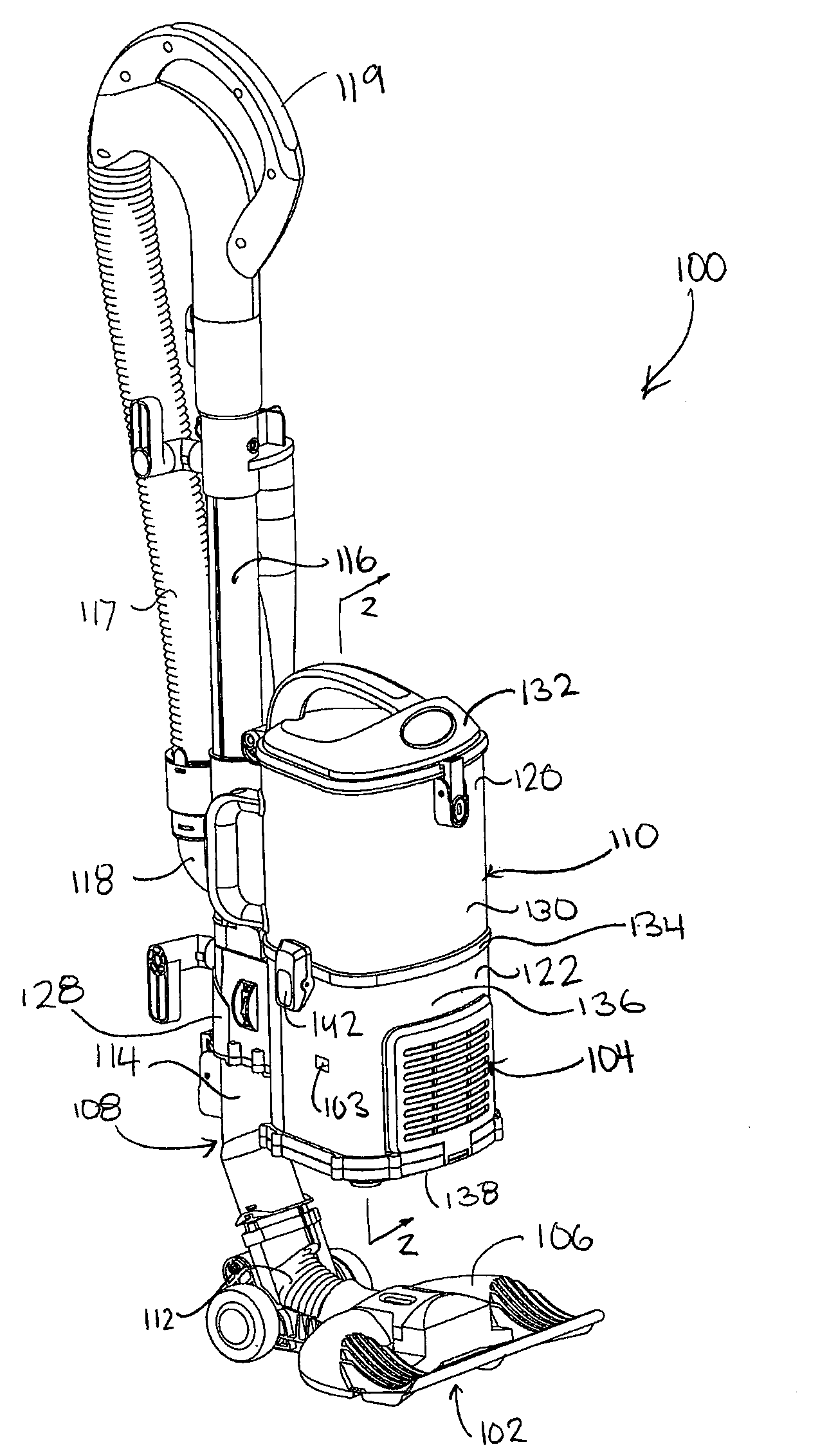
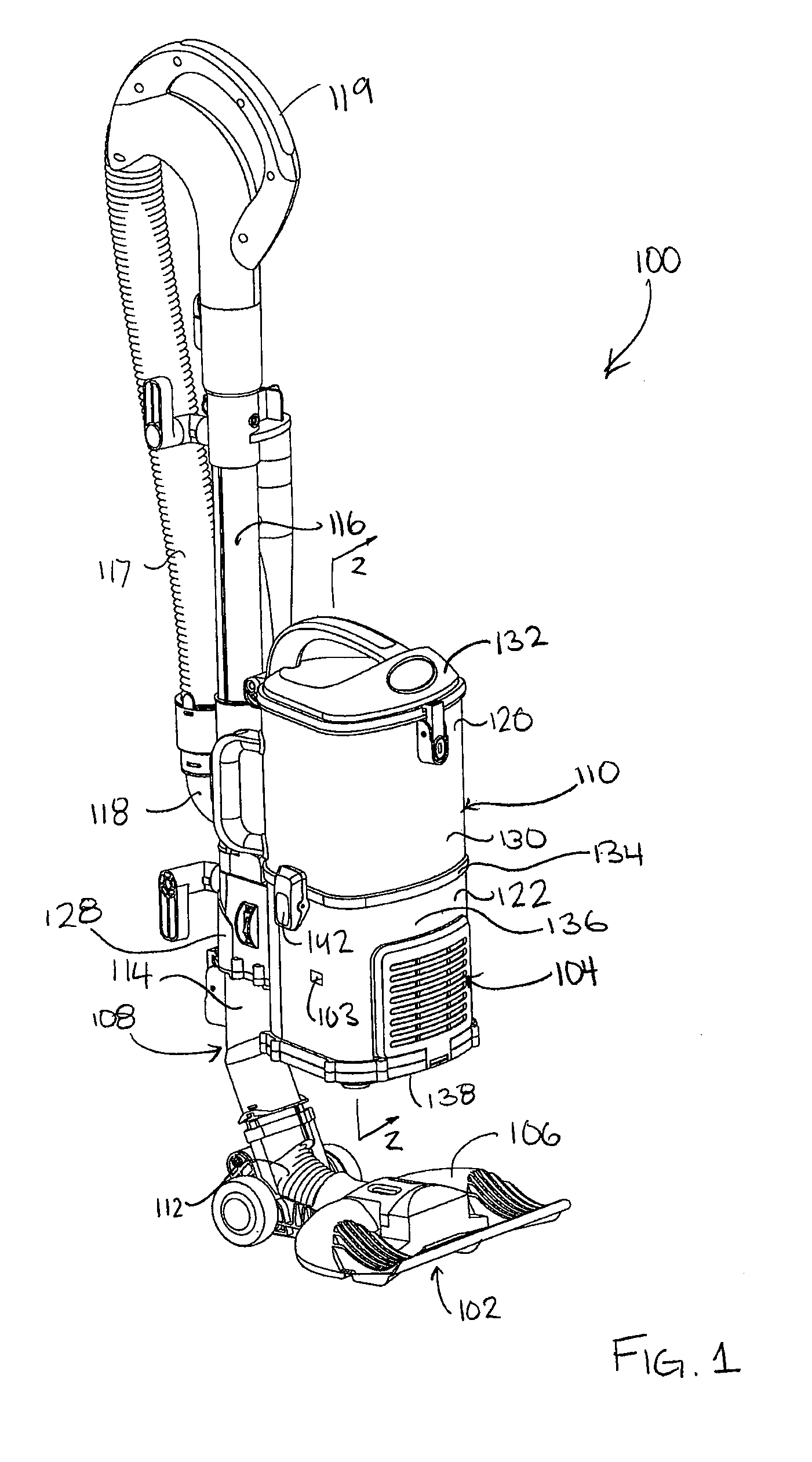
[0036]Referring to FIG. 1, a first embodiment of a surface cleaning apparatus 100 is shown. In the embodiment shown, the surface cleaning apparatus 100 is an upright vacuum cleaner. In alternate embodiments, the surface cleaning apparatus may be another suitable type of surface cleaning apparatus, such as a canister type vacuum cleaner, and hand vacuum cleaner, a stick vac, a wet-dry type vacuum cleaner or a carpet extractor.

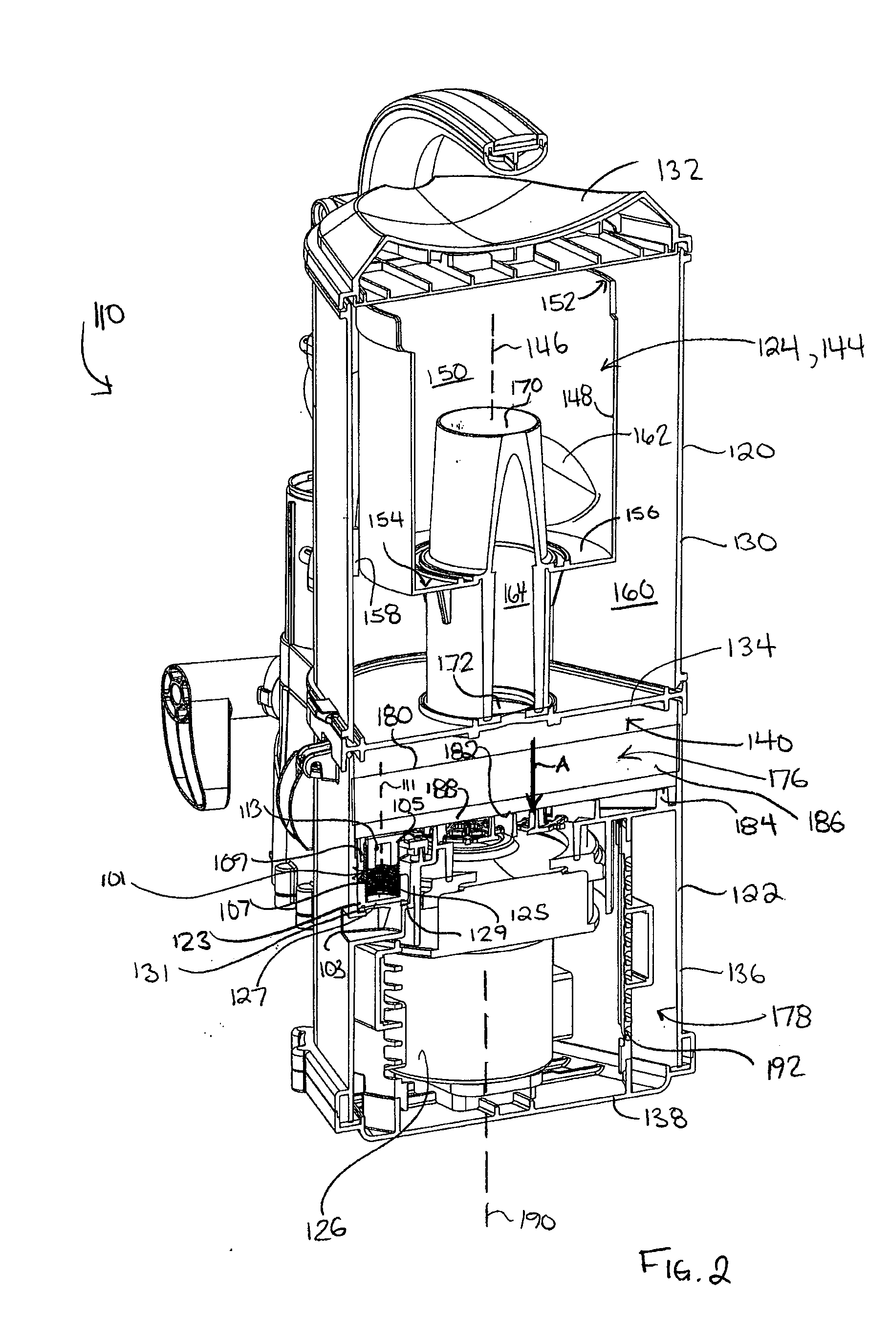
[0037]Referring still to FIG. 1, the surface cleaning apparatus 100 has a dirty air inlet 102, a clean air outlet 104, and an air flow passage or pathway extending therebetween. In the embodiment shown, the dirty air inlet 102 is provided in a floor cleaning head, for example surface cleaning head 106. From the dirty air inlet 102, the airflow passage extends through the surface cleaning head 106, and through an air conduit 108, to a cleaning unit, for example a suction and filtration unit 110. The clean air outlet 104 is provided in the suction and filtration u...


PUM


Abstract

An upright surface cleaning apparatus comprises a floor cleaning head having a dirty air inlet and an upright section moveably mounted to the surface cleaning head. The surface cleaning apparatus also includes an air flow passage extending from the dirty air inlet to a clean air outlet. The air flow passage includes a conduit section. The surface cleaning apparatus also includes a suction motor and an air treatment member positioned in the air flow passage, provided in one of the floor cleaning head and the upright section. The conduit section has an inlet end and an outlet end. The inlet end is rotatably connected to the air flow passage about an axis parallel to air flow through the inlet end, and the outlet end is rotatably connected to the air flow passage about an axis parallel to air flow through the outlet end.

Description

FIELD[0001]This disclosure relates to surface cleaning apparatuses, such as vacuum cleaners. Particularly, the disclosure relates to an air flow passage including a conduit section having two rotatable connections.INTRODUCTION[0002]The following is not an admission that anything discussed below is prior art or part of the common general knowledge of persons skilled in the art.[0003]Various constructions for surface cleaning apparatus such as vacuum cleaners are known. Currently, many surface cleaning apparatus are constructed using at least one cyclonic cleaning stage. The air is drawn into the vacuum cleaner through a dirty air inlet and conveyed to a cyclone inlet. The rotation of the air in the cyclone results in some of the particulate matter in the airflow stream being disentrained from the airflow stream. This material is then collected in a dirt collection chamber, which may be at the bottom of the cyclone or in a dirt collection chamber exterior to the cyclone chamber (see f...

Claims


Application Information

Patent Timeline
IPC IPC(8): A47L9/00
CPCA47L5/225A47L9/1666A47L9/242A47L9/1608A47L9/1683A47L9/122
Inventor CONRAD, WAYNE ERNEST
Owner OMACHRON INTPROP
Learn More