Method and apparatus for controlling temperature in a cryocooled cryostat using static and moving gas

a technology of static and moving gas and cryostat, which is applied in the direction of domestic cooling apparatus, container discharge methods, separation processes, etc., can solve the problems of limiting modularity and use of measurement systems, affecting the efficiency of measurement systems, and affecting the overall system complexity and cost, so as to operation, reduce the cost of helium replenishment, and reduce the cost of maintenan

Active Publication Date: 2011-09-15
QUANTUM DESIGN
View PDF29 Cites 42 Cited by
  • Summary
  • Abstract
  • Description
  • Claims
  • Application Information

AI Technical Summary

Benefits of technology

[0014]Such arrangement allows simultaneous temperature sweeping and control of the sample specimen (between 400 K and down to below 2 K) and also cooling of a high-field superconducting magnet using a single multistage, helium-temperature cryogenic cooler that does not rely on the prior art physical links, cryogenic moving parts, and mechanical valves for heat distribution and control. The present system offers rapid initial cool-down (24 hours or less) with very little externally supplied helium gas, and is able to operate for extended periods of time without requiring maintenance and with minimal, if any, helium replenishment. While the system generally operates with liquid helium at the bottom of the cryogenic cooler, gaseous helium at about 4.2 k can be sufficient.
[0015]The apparatus of the invention embodiments specifically addresses removal of the large heat load generated by the sweeping superconducting magnet by providing very high conductivity links (solid plates and posts) between the liquid coolant at the bottom part of the cooler chamber and the magnet top-flange. The structure of the cryostat of embodiments of the present invention avoids the commonly used flexible copper links by employing a thermosiphon effect and therefore simplifies the design of the cryostat and provides for larger thermal conductance between the cooling apparatus and the rest of the cryostat.

Problems solved by technology

The use of flexible physical links or fixed heat exchangers limits modularity and uses of the measurement system, as the physical links place an upper limit on the heat exchange between the PTC and the other cryostat elements and additional thermal couplings may be necessary if increased heat exchange rate is required.
Overall, physical coupling between the cryogenic cooler and the rest of the cryostat substantially complicates maintenance and increases the overall system complexity and cost.
Therefore, a system employing physical links transfers superfluous vibration energy from the PTC into the sample area which can be detrimental in applications that are particularly sensitive to small motions, such as optical interferometry, where special care needs to be taken to prevent vibration energy of the PTC from contaminating the sample signal.
This approach increases system complexity and costs while limiting flexibility of use as the re-condenser unit needs to be in physical contact with the PTC.
However, the difficulty of constructing reliable low temperature valves has limited the usefulness of this approach.
Although such design allows for smooth temperature regulations in the sample chamber over the desired range it increases cost and complexity of the measurement apparatus and does not address the need of delivering additional cooling power to the superconducting magnet when the latter is operated in sweeping mode.

Method used


Image

  • Method and apparatus for controlling temperature in a cryocooled cryostat using static and moving gas
  • Method and apparatus for controlling temperature in a cryocooled cryostat using static and moving gas
  • Method and apparatus for controlling temperature in a cryocooled cryostat using static and moving gas

Examples


Embodiment Construction

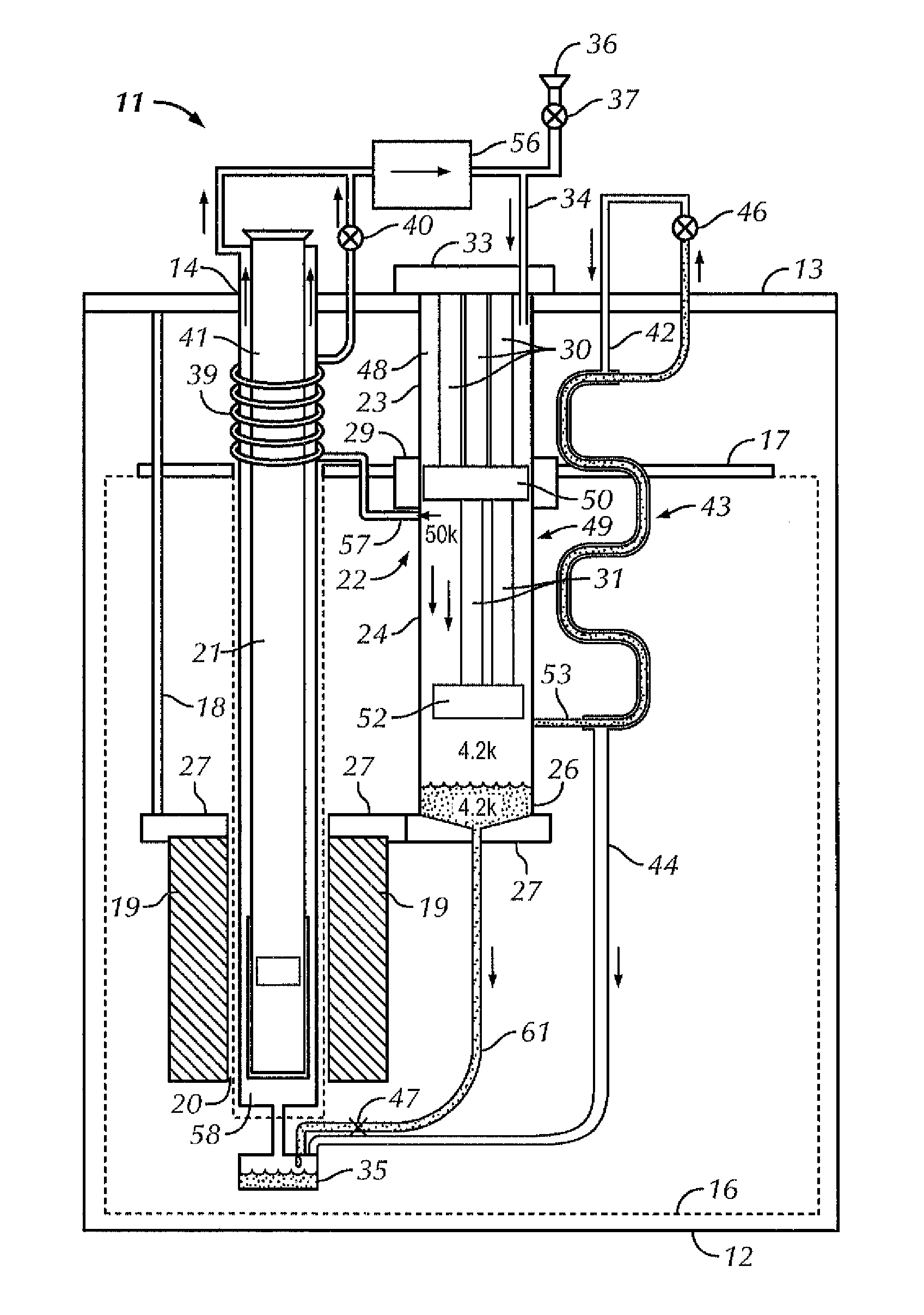
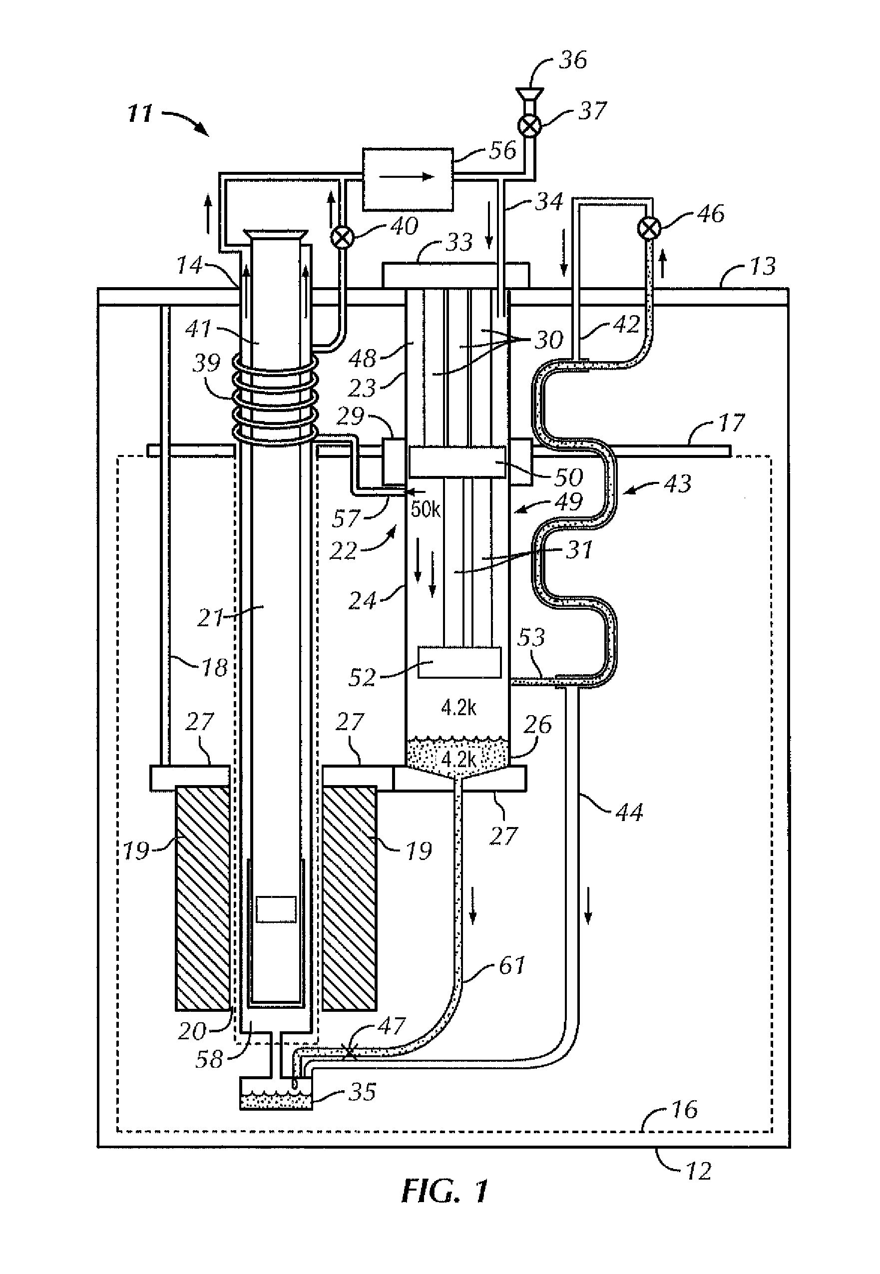
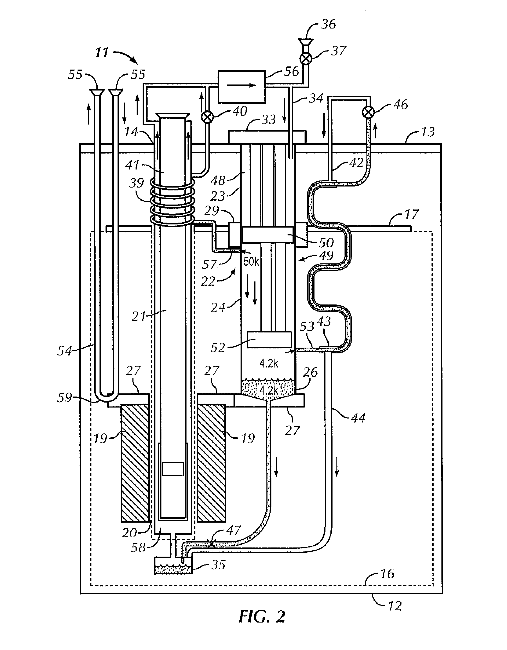
[0013]In a system for temperature regulation which embodies the principles of the invention, a varying magnetic field is generated by a superconducting magnet. In one embodiment, the temperature in a sample chamber is controlled under a variety of temperature ranges by selectively transferring the cooling power from the cryogenic cooler assembly to the different areas within the system apparatus. The magnet assembly is maintained at an approximately constant temperature of 4.2 K, at least in part, by solid conduction contact with a thermally conductive element which is cooled by gaseous or liquid helium that is condensed by the cryogenic cooler.

[0014]Such arrangement allows simultaneous temperature sweeping and control of the sample specimen (between 400 K and down to below 2 K) and also cooling of a high-field superconducting magnet using a single multistage, helium-temperature cryogenic cooler that does not rely on the prior art physical links, cryogenic moving parts, and mechanic...


PUM

PropertyMeasurementUnit
temperatureaaaaaaaaaa
temperaturesaaaaaaaaaa

Abstract

A cryostat for providing temperature regulation, one purpose being measuring physical properties of materials, the cryostat employing a superconducting magnet assembly for generating variable magnetic field in the sample space and a cryogenic cooler for cooling the sample space. The cryogenic cooler chamber configuration provides for efficient heat exchange between different stages of the cryogenic cooler without the need for physical heat links. This construction enables selective delivery of cooling power from the cryogenic cooler to the desired areas within the cryostat without using flexible physical thermal links. A counter flow exchanger and ambient temperature valves facilitate efficient use of the cryogenic cooler stages. The removal of large heat load generated by the superconducting magnet while operating in the sweeping mode is achieved, in part, by employing a solid plate thermal coupling element between the cryogenic cooler chamber and the magnet assembly.

Description

BACKGROUND[0001]1. Field of the Invention[0002]The present invention relates generally to temperature regulation in a cryostat, with an exemplary purpose of the use of such a cryostat as an apparatus and a method for regulating temperature in a cryogenic measurement chamber, while cooling a superconducting magnet, using a cryogenic cooler as a source of refrigeration.[0003]2. Discussion of the Prior Art[0004]Systems have been available to employ cryostats for temperature regulation in the cryogenic temperature region. One use of such cryostats is to test the physical properties of specimens. The need for testing physical properties of specimens of various types for different properties has increased substantially over the last several years. Systems exist for characterizing the physical properties of various materials under variable measurement conditions by programming an arbitrary sequence of temperature and magnetic field sweeps and steps at which to characterize various physical...

Claims


Application Information

Patent Timeline
Patent Type & Authority Applications(United States)
IPC IPC(8): F25B21/00F25B25/00B01D8/00F25B29/00F25B45/00
CPCF17C13/007F25B9/10F25D19/006F25B2400/17F25B9/145F17C3/085F17C13/006F17C2223/043F17C2227/0383F17C2270/0509F17C2270/0527
Inventor BLACK, RANDALLMARTIEN, DINESHNEILS, WILLIAMDIEDERICHS, JOST
Owner QUANTUM DESIGN
Why Eureka
Try Eureka