Composite laminate structure

a laminate structure and composite material technology, applied in the field of composite laminate structure, can solve the problems of structure weakening and eventually failing, delamination, and adding to the effect of delamination

Active Publication Date: 2011-09-15
AIRBUS OPERATIONS LTD
View PDF74 Cites 16 Cited by
  • Summary
  • Abstract
  • Description
  • Claims
  • Application Information

AI Technical Summary

Benefits of technology

[0008]The fracture provides permanent visible evidence of impact damage, for instance by cracking or by one or more pieces breaking off from the impact indicator. As

Problems solved by technology

While the structures may be strong when loaded in the way in which they have been designed to be loaded, they may be vulnerable to impact damage, which may result in delamination occurring.
Delamination may result in the structure weakening and eventually failing.
Particularly vulnerable are the edges of composite laminate structures (at which the layers of the composite laminate structure terminate) where an impact occurs, particularly if the impact is end-on (i.e. when the impact is in a direction perpendicular to the edge and parallel to the plane of the laminates that make up the structure).
If an impact has a significant component of force in the end-on direction the impact may be capable of damaging the bonding between the laminate's layers co

Method used


Image

  • Composite laminate structure
  • Composite laminate structure
  • Composite laminate structure

Examples


Embodiment Construction

)

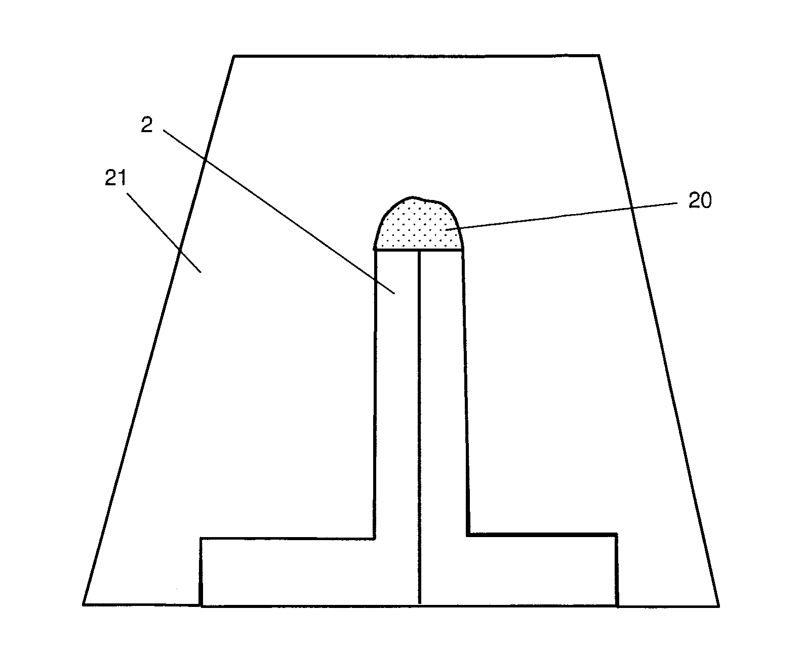
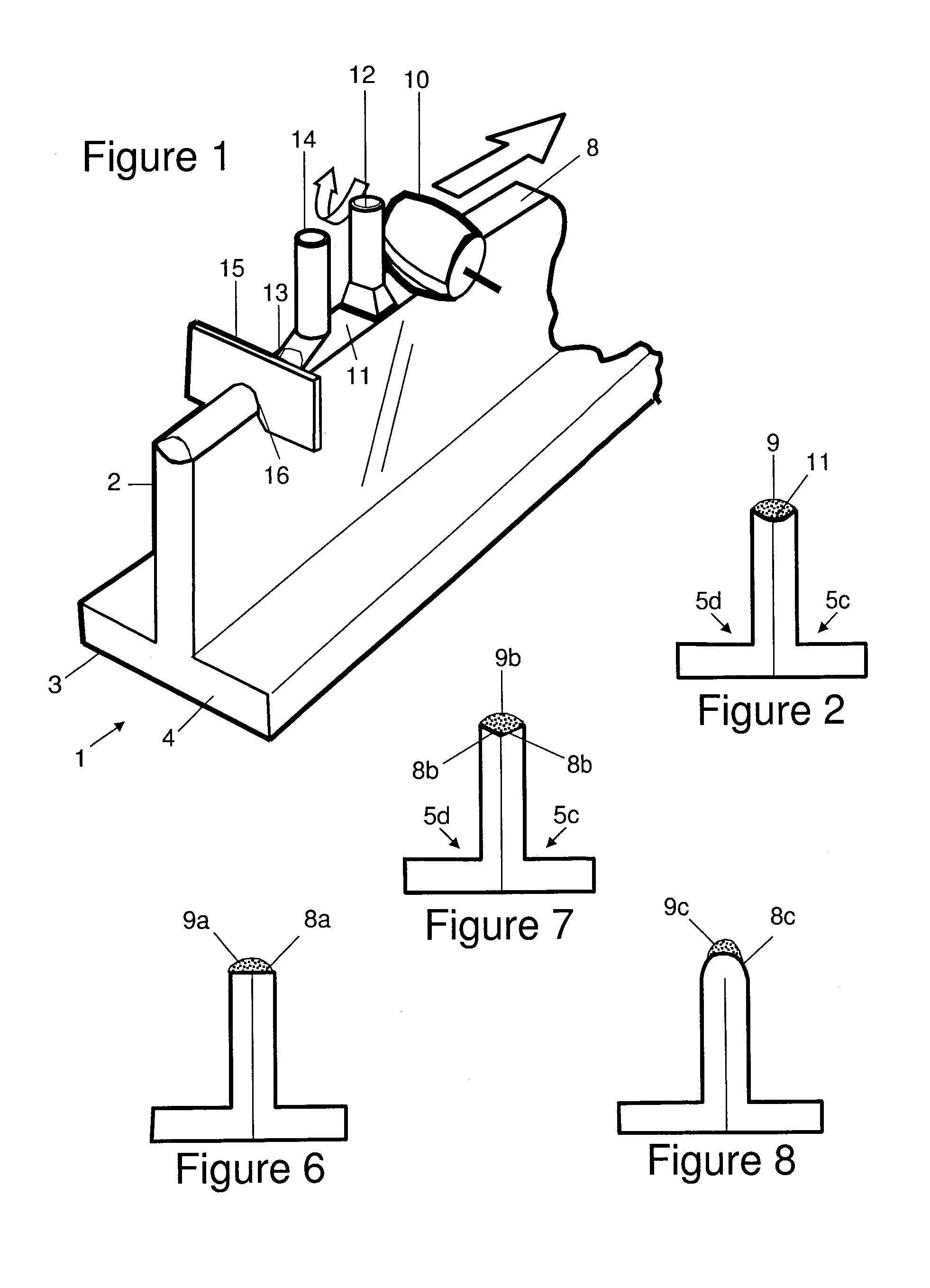
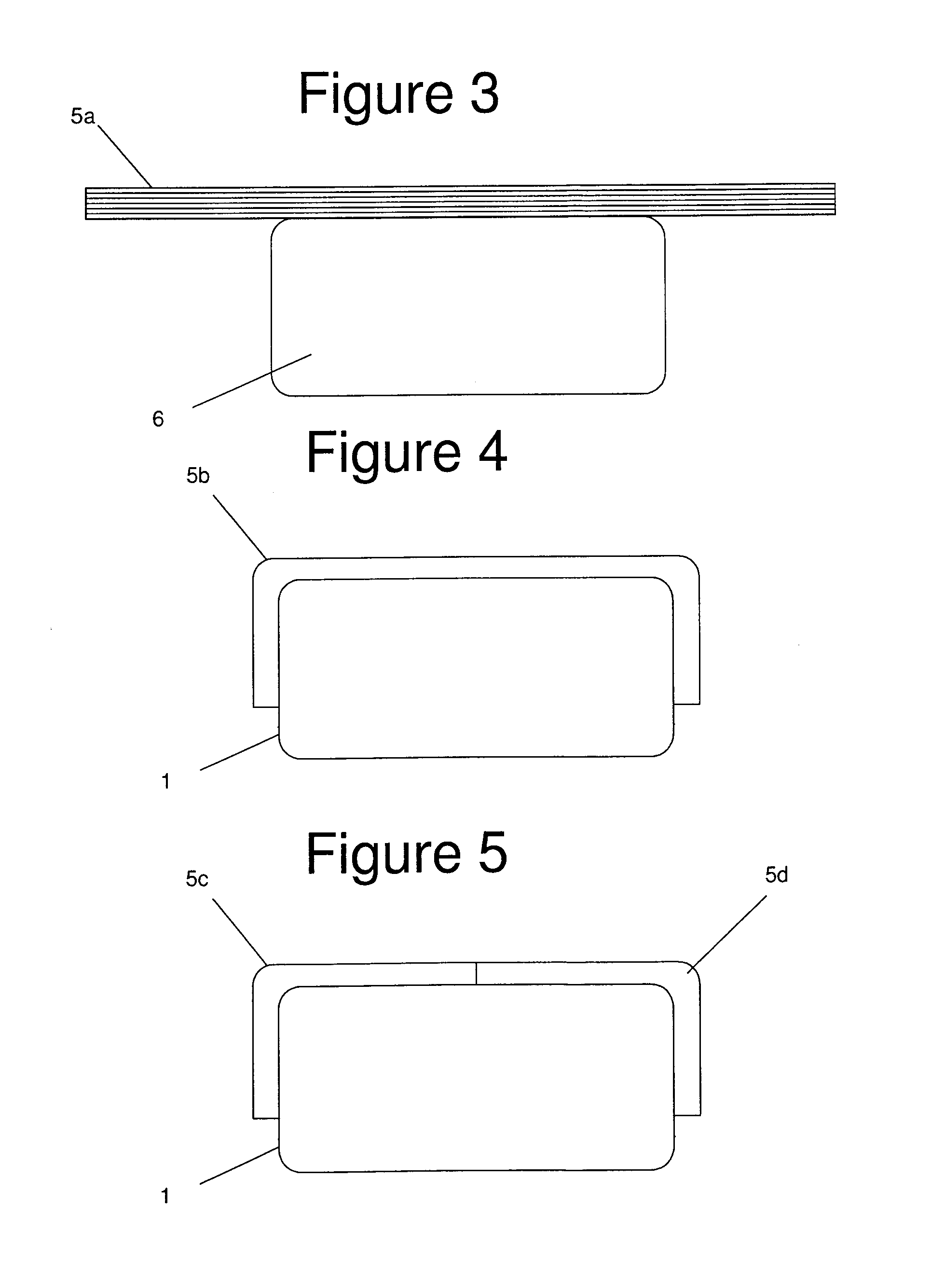
[0026]A stringer 1 shown in FIG. 1 comprises a blade 2 and a pair of flanges 3,4. The stringer is formed by the process illustrated in FIGS. 3-5. In a first step, a planar charge 5a is placed on a male forming tool 6. The charge 5 comprises a laminate structure formed from a stack of sheets, each sheet comprising a plurality of unidirectional carbon fibres impregnated by a thermosetting epoxy resin. These sheets are conventionally known as “prepregs”. Individual prepreg sheets are shown schematically in FIG. 3 but not in the other figures for purposes of clarity.

[0027]The charge 5a is then deformed over the mould tool as shown in FIG. 4 to form a U-shaped part 5b. The U-shaped part 5b is then cut into two L-shaped parts 5c,5d as shown in FIG. 5; and the parts 5c,5d are placed back-to-back as shown in FIG. 2. Once the L-shaped parts 5c,5d have been placed back-to-back, they are co-cured to harden the stringer and join the parts together.

[0028]The direction of the length of the strin...


PUM

PropertyMeasurementUnit
Temperatureaaaaaaaaaa

Abstract

A structure comprising a composite laminate having an edge; and an impact indicator which is carried by the edge and comprises a resin which fractures upon impact. The fracture provides permanent visible evidence of impact damage, for instance by cracking or by one or more pieces breaking off from the impact indicator. As well as providing such visible evidence of impact damage, the impact indicator may also provide an element of impact protection. Typically the impact indicator is formed from a resin which is more brittle and less strong than the material forming the composite laminate. For instance the material forming the composite laminate may be reinforced, and the resin forming the impact indicator may be un-reinforced.

Description

FIELD OF THE INVENTION[0001]The present invention relates to a composite laminate structure, and a method for indicating impact damage in such a structure. In particular, although not exclusively, the structure may form part of an aircraft component.BACKGROUND OF THE INVENTION[0002]Many aircraft components are made from composite laminate materials. For example, a stringer in an aircraft wing, stiffeners and spar structures, may all be in the form of composite laminate structures. While the structures may be strong when loaded in the way in which they have been designed to be loaded, they may be vulnerable to impact damage, which may result in delamination occurring. Delamination may result in the structure weakening and eventually failing. Particularly vulnerable are the edges of composite laminate structures (at which the layers of the composite laminate structure terminate) where an impact occurs, particularly if the impact is end-on (i.e. when the impact is in a direction perpen...

Claims


Application Information

Patent Timeline
IPC IPC(8): G01L5/00B05D1/26B29C70/78B32B3/04B32B3/02B32B7/02
CPCB29C70/763B29K2995/0089B64C1/064B64C1/065Y10T428/2419B64C3/185B64C2001/0072Y02T50/433Y10T428/24777B64C3/182B64F5/60Y02T50/40G01L5/0052G01M5/0091G01M11/081G01L1/24G01M11/08
Inventor KAYE, ALLANLI, DONG
Owner AIRBUS OPERATIONS LTD
Why Eureka
Try Eureka