Method of clinching the top and bottom ends of Z-axis fibers into the respective top and bottom surfaces of a composite laminate

a technology of z-axis fibers and composite laminates, which is applied in the direction of manufacturing tools, transportation and packaging, and transportation, etc., can solve the problems of core failure under compressive force, failure of bond or adhesive capability, and failure of laminate structure, so as to achieve convenient deployment and assembly and easy handling

Inactive Publication Date: 2002-10-10
EBERT COMPOSITES
View PDF0 Cites 51 Cited by
  • Summary
  • Abstract
  • Description
  • Claims
  • Application Information

AI Technical Summary

Benefits of technology

[0015] It is an object of the invention to provide a novel improved composite laminate structure that has riveted or clinched 3-D groupings of fiber filaments as part of the structure to provide improved resistance to delaminating of the skins or delaminating of the skins to core structure.
[0020] It is another object of the invention to provide a preferred embodiment of a temporary runway, taxiway, or ramp for military aircraft. This composite laminate structure would replace current heavier aluminum structure, (known as matting) and could easily be deployed and assembled. The 3-D Z-axis reinforcements ensure the panels can withstand the full weight of aircraft tire loads, yet be light enough for easy handling.

Problems solved by technology

Typical failures in laminate structure can result from core failure under compressive forces or in shear or, most commonly, from a failure of the bond or adhesive capability between the core and the composite skins (also known as face sheets).
Other failures, depending on loading may include crimpling of one or both skins, bending failure of the laminate structure, or failure of the edge attachment means from which certain loads are transferred to the laminate structure.
Once cured these 2-D layers are 2-D laminates and when failure occurs in this cured composite, the layers typically fail and this is known as interlaminar failure.
Practically, these reinforcements are pins or rods and require a certain stiffness to be forced into the skin or face layers.
This cannot be possible unless the Z-directional or 3-D reinforcements are cured composite or metallic pins.
It is impossible to drive a virgin glass fiber tow, or grouping of fiber filaments, as it is shipped from a glass manufacturer such as Owens Coming, through a face sheet.
This is a poor way to attempt to tie the core to the skins, as the fillet will be significantly weaker than if the interior fiber penetrated the skins.
That is, the interior uncured fabric in Day's patent is limp and cannot be "driven" into the skins or face sheets without being rigid.
This would only be possible with a thermoplastic composite that is already cured and certain weaknesses develop from remelting a thermoplastic matrix after the first solidification.
And many of the techniques referenced will not work with cores that don't crush like foam.
All prior art processes referenced have a degree of manual labor involved and have been only successful to date where aerospace is willing to pay the costs for this manual labor.
None of the existing processing techniques referenced can compare to that performance-to-cost ratio.

Method used


Image

  • Method of clinching the top and bottom ends of Z-axis fibers into the respective top and bottom surfaces of a composite laminate
  • Method of clinching the top and bottom ends of Z-axis fibers into the respective top and bottom surfaces of a composite laminate
  • Method of clinching the top and bottom ends of Z-axis fibers into the respective top and bottom surfaces of a composite laminate

Examples


Embodiment Construction

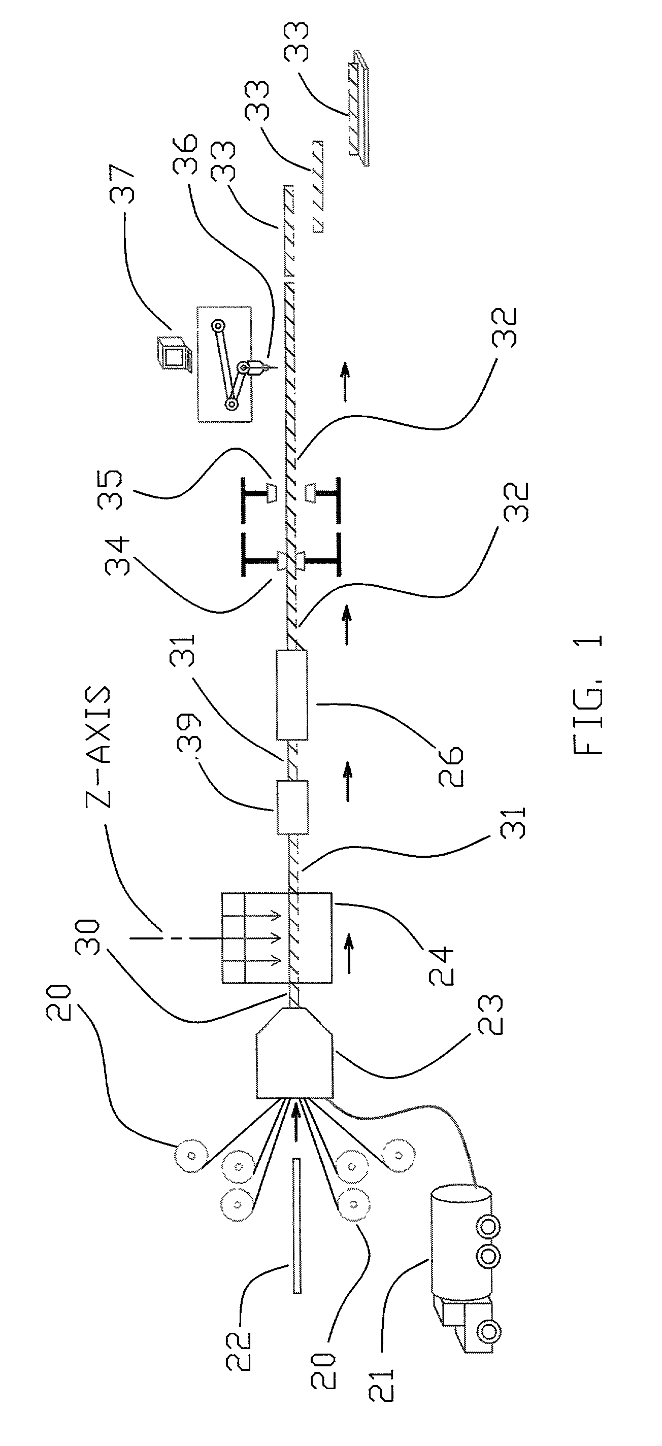
[0029] FIG. 1 illustrates a method and application for forming a pultruded and clinched 3-D Z-axis fiber reinforced composite laminate structure. The pultrusion direction is from left-to-right in FIG. 1 as shown by the arrows. The key components of the apparatus will become evident through the following description.

[0030] Shown in FIG. 1 are the grippers 34 and 35. These are typically hydraulically actuated devices that can grip a completely cured composite laminate panel 32 as it exits pultrusion die 26. These grippers operate in a hand-over-hand method. When gripper 34 is clamped to the panel 32, it moves a programmed speed in the direction of the pultrusion, pulling the cured panel 32 from the die 26. Gripper 35 waits until the gripper 34 has completed its full stroke and then takes over.

[0031] Upstream of these grippers, the raw materials are pulled into the die in the following manner. It should be recognized that all of the raw material is virgin material as it arrives from va...


PUM

PropertyMeasurementUnit
densityaaaaaaaaaa
densityaaaaaaaaaa
compressive strengthaaaaaaaaaa

Abstract

A method and apparatus for forming an improved pultruded and clinched Z-axis fiber reinforced composite laminate structure. The upper and lower skins and the core are pulled automatically through tooling where the skin material is wetted-out with resin and the entire composite laminate is preformed in nearly its final thickness. The preformed composite laminate continues to be pulled into an automatic 3-dimensional Z-axis fiber deposition machine that deposits "groupings of fiber filaments" at multiple locations normal to the plane of the composite laminate structure and cuts each individual grouping such that a extension of each "grouping of fiber filaments" remains above the upper skin and below the lower skin. The preformed composite laminate then continues to be pulled into a secondary wet-out station. Next the preformed composite laminate travels into a pultrusion die where the extended "groupings of fiber filaments" are all bent over above the top skin and below the bottom skin producing a superior clinched Z-axis fiber reinforcement as the composite laminate continues to be pulled, catalyzed, and cured at the back section of the pultrusion die. The composite laminate continues to be pulled by grippers that then feed it into a gantry CNC machine that is synchronous with the pull speed of the grippers and where computerized machining, drilling, and cutting operations take place. This entire method is accomplished automatically without the need for human operators.

Description

REFERENCE TO RELATED APPLICATION[0001] This application claims the priority of provisional patent application 60 / 281838 filed on Apr. 6, 2001 and provisional patent application, 60 / 293939 filed on May 29, 2001. This application also claims the priority of U.S. patent application Ser. No. 09 / 922,053 filed Aug. 2, 2001.[0002] The present invention relates to an improvement in the field of composite laminate structures known as sandwich structures formed with outside skins of a polymer matrix composite and an internal core of either foam, end-grain balsa wood, or honeycomb, and more specifically to the field of these sandwich structures which additionally have some type of Z-axis fiber reinforcement through the composite laminate and normal to the plane of the polymer matrix composite skins.[0003] There is extensive use in the transportation industry of composite laminate structures due to their lightweight and attractive performance. These industries include aerospace, marine, rail, a...

Claims


Application Information

Patent Timeline
Patent Type & Authority Applications(United States)
IPC IPC(8): B29C70/08B29C70/24B32B5/02E01C9/08E04C2/296
CPCB29C70/086B29C70/088B29C70/24B32B5/02Y10T29/49957E04C2/296Y10S411/904Y10T428/233Y10T428/24174E01C9/086Y10T428/249924Y10T428/31504Y10T428/249942Y10T428/23914Y10T428/249923
Inventor JOHNSON, DAVID W.HOOK, JAMES M.GARRETT, SCOTT A.MOYERS, STEVEN G.
Owner EBERT COMPOSITES
Why Eureka
Try Eureka