Method For Fabricating A Curved Beam From Composite Material

a composite material and beam technology, applied in the field of beam fabrication, can solve the problems of degrading the strength of the finished beam, wasting a lot of material, and difficult to get a laminate composed of layers of fibers with different fiber directions to follow the curvature, so as to achieve good strength and reduce material was

Inactive Publication Date: 2006-09-28
SAAB AB
View PDF12 Cites 48 Cited by
  • Summary
  • Abstract
  • Description
  • Claims
  • Application Information

AI Technical Summary

Benefits of technology

[0008] The method according to the invention makes it possible to fabricate a beam with very little waste of material. Because the beam can be fabricated with no weak points in the form of slits, a beam with good strength properties is obtained.

Problems solved by technology

One problem associated with the fabrication of curved beams using this type of tool is that it is difficult to get a laminate comprised of layers of fibers with different fiber directions to follow the curvature of the beam when the curvature is large, i.e. the radius of curvature R is small.
However, this entails a major waste of material and degraded strength in the finished beam.
However, one disadvantage of such supporting layers is that they increase the weight of the finished beam, which is undesirable, particularly in an aviation context.

Method used


Image

  • Method For Fabricating A Curved Beam From Composite Material
  • Method For Fabricating A Curved Beam From Composite Material
  • Method For Fabricating A Curved Beam From Composite Material

Examples


Embodiment Construction

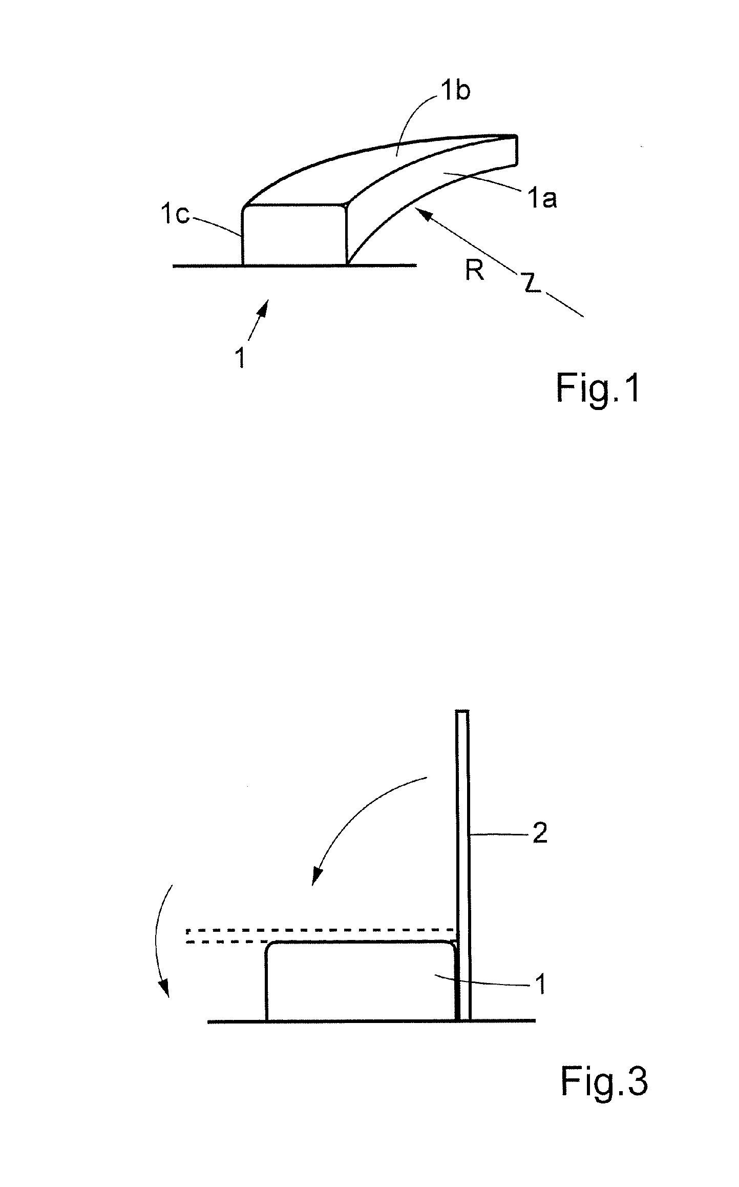
[0013] The invention will be described below based on an embodiment in which the curved beam is shaped as a C-beam. It will be apparent that the same fabrication method can also be used for hat-shaped beams, Z-beams and I-beams.

[0014]FIG. 1 shows a perspective view of a male tool with a radius of curvature R. The tool can preferably consist of a homogeneous metal tool. Other materials and structures are of course also possible. The method according to the invention has been tested successfully using curve radii in excess of 2 meters and beam heights of up to 150 mm. It will be apparent to one skilled in the art that larger radii make it possible to work with higher beam heights while, in the same way, lower beam highs make it possible to work with smaller curve radii.

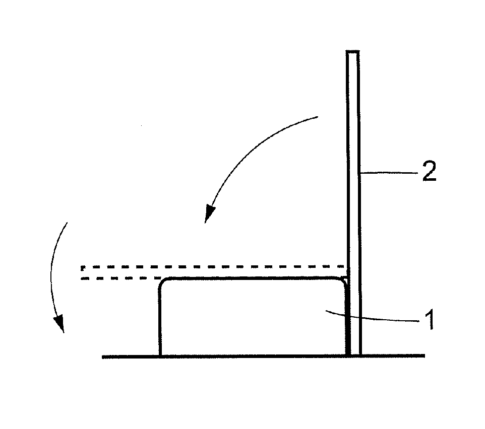
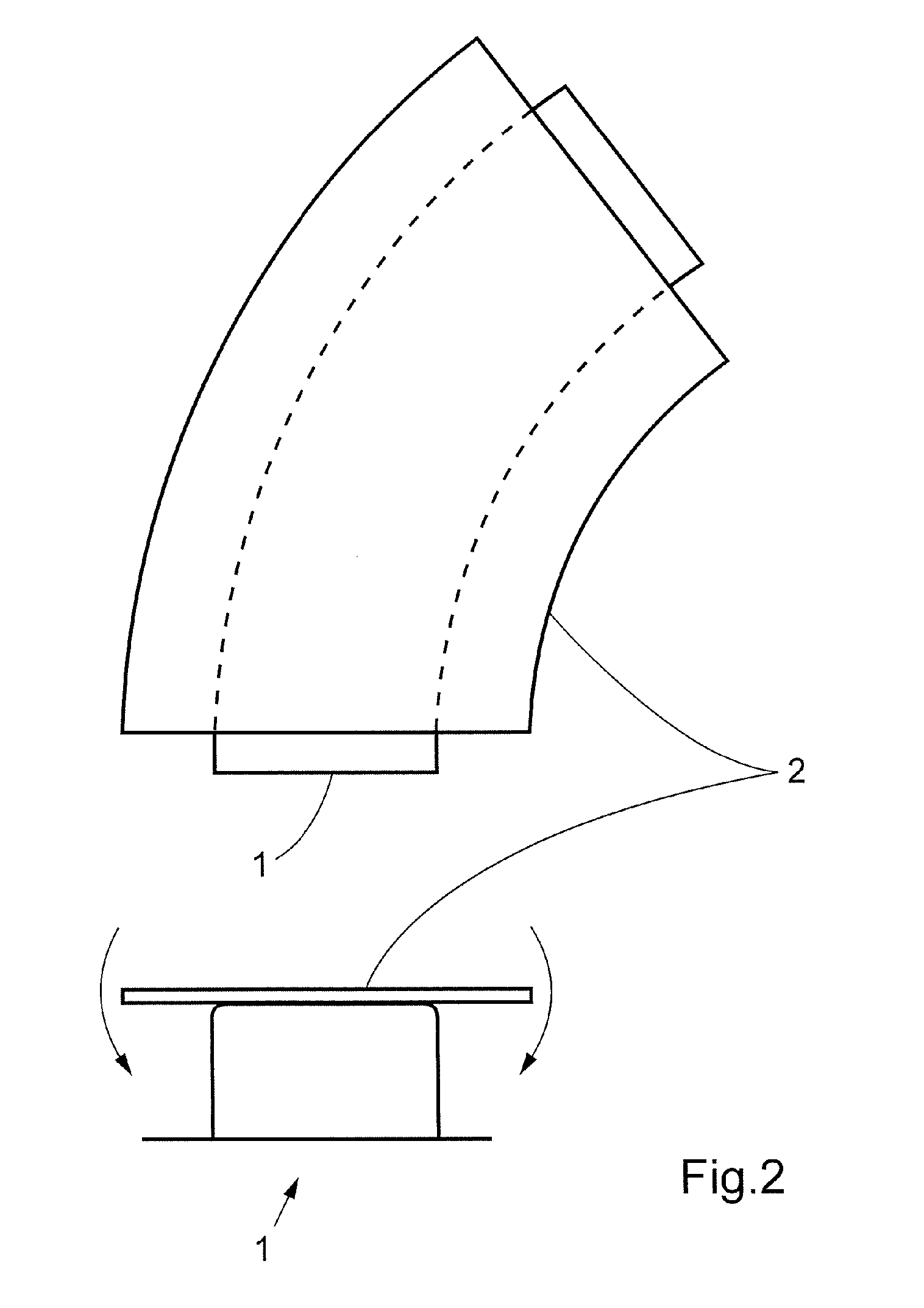
[0015]FIG. 2 depicts the shaping of a laminate 2 on a male tool 1 according to a prior art method. The laminate 2 is laid in contact with an intermediate web on the tool. The fiber composite laminate 2 is then brought...


PUM

PropertyMeasurementUnit
heightsaaaaaaaaaa
radius of curvatureaaaaaaaaaa
densityaaaaaaaaaa

Abstract

This invention concerns a method for fabricating a curved beam from fiber composite material. A flat fiber composite laminate (2) comprising a plurality of layers and at least two different fiber directions is formed. The fiber composite laminate (2) is disposed in contact with a male tool (1) comprised of a first flange (1a), a second flange (1c) and an intermediate web (1b), which male tool (1) is curved in its longitudinal direction with a radius of curvature R in such a way that the first flange (1a) has a shorter longitudinal extent than the second flange (1c). The fiber composite laminate (2) is brought into contact with and secured to the first flange (1a) of the male tool (1). The male tool (1) and the fiber composite laminate (2) are then rotated relative to one another so that the fiber composite laminate (2) is brought into contact with the intermediate web (1b) of the male tool (1) in a first rotational movement, and brought into contact with the second flange (1c) of the male tool (1) in a second rotational movement. The fiber composite laminate (2) hardens on the male tool (1), and the finished beam is separated from the tool (1). The invention also relates to a beam of fiber composite material fabricated according to the method.

Description

FIELD OF THE INVENTION [0001] The invention concerns a method for fabricating a curved beam from fiber composite material. A flat fiber composite laminate comprising a plurality of layers and at least two different fiber directions is formed using the method according to the invention. The fiber composite laminate is disposed against a male tool comprising a first flange, a second flange and an intermediate web. The male tool is curved in its longitudinal direction with an angle of curvature R in such a way that the first flange has a shorter longitudinal extent than the second flange. [0002] The invention also concerns a beam fabricated using the method according to the invention. BACKGROUND OF THE INVENTION [0003] There is major demand for extended beams that combine low weight with high strength, particularly in the aviation industry. Meter-long beams are made from fiber composite material to support curved structures in aircraft fuselages. These fiber composite beams are given a...

Claims


Application Information

Patent Timeline
Patent Type & Authority Applications(United States)
IPC IPC(8): B32B1/00
CPCB29C70/32B29C70/38B29C70/386B29C70/541Y10T156/1043Y10T428/24628Y10T428/24124Y10T156/1036Y02T50/433Y02T50/40
Inventor WEIDMANN, BJORNRUDQVIST, CLAESKROGAGER, MAXPETERSSON, MIKAEL
Owner SAAB AB
Why Eureka
Try Eureka