Composite laminate manufacture with multiaxial fabrics

a composite laminate and multi-axial technology, applied in weaving, transportation and packaging, spars/stringers, etc., can solve the problems of a large number of "passes" of the tape head, a large number of tape head passes, and a very complex structure of the optimized aircraft wing, etc., to achieve the effect of high strength, low modulus and high modulus

Inactive Publication Date: 2002-04-16
AIRBUS OPERATIONS LTD
View PDF11 Cites 43 Cited by
  • Summary
  • Abstract
  • Description
  • Claims
  • Application Information

AI Technical Summary

Benefits of technology

The multiaxial fabrics, in addition to comprising differing fibre orientations from ply to ply, may also have fibres whose modulus differs from ply to ply. The effect of this form of design tailoring is to allow the modulus of a laminate to differ according to the direction of applied force. For example, in an aircraft wingskin stringer, the use of higher modulus fibres in the lengthwise / 0 deg / warp direction and high strength (lower modulus) fibres in the plus or minus 45 deg and 90 deg / weft directions allows the use of thinner unidirectional plies and hence lower overall mass, as compared to a stringer made entirely from high strength fibres. In this context the higher modulus "IM" fibres may comprise carbon fibres of approximately 300 GPa and approximately 2% strain; high strength "HS" fibres may be carbon fibres of approximately 240 GPa and approximately 1.5-2% strain.
For an aircraft wingskin application a suitable use of fibres may be HS in the 0 deg / warp / spanwise direction and IM in the plus or minus 45 deg and in the 90 deg directions. This combination allows greater torsional stiffness with lower mass without an increase in spanwise stiffness which may be detrimental to gust load characteristics of the wing.

Problems solved by technology

An optimised aircraft wing, especially one made of carbon fibre based composite, is a very complex structure due to the variety of functions required of different types of wing component, eg. skins, stringers, ribs and spars.
However the layup process for a large thick structure is very slow for a number of reasons.
Firstly, as 4 to 8 layers of tape are required for every 1 mm of laminate thickness, a very large number of "passes" of the tape head can be required.
Secondly, in order to lay up the tape in the required fibre orientations (the fibre orientation of the tape itself is always lengthwise), the tape laying head will need to move across the layup in all those directions of orientation, thus requiring an expensive head movement apparatus and complex computer software.
Hence, to lay up a laminate of the size and shape of a modern passenger aircraft wing requires both very expensive tape laying apparatus and a long layup time.
Also the amount and cost of scrap consumables, eg. release paper, can be high for tape laying methods.
A complex laminate such as an aircraft wingskin formed from a single multiaxial fabric style would be likely to suffer an unacceptable weight penalty caused by the inability of that style to provide the optimum ratio of fibre orientations in a given part of the laminate efficiently to react the particular stresses applied to that part.
In addition, the use of a single multiaxial fabric style can result in excessive stress concentrations at ply "dropoffs".
One reason for increased costliness of using multiple multiaxial fabric designs is that for each fabric style, qualification and ultimately certification by the relevant aviation authority would be necessary, thus adding to the overall design, manufacture and certification cost of the layup.
Even if fabrics are dedicated to particular layups it has not been easy to change from one to another in the same laminate.
The triaxial fabrics are preferably stitched for handling and permeability reasons, whereas the unidirectional fabrics are often bindered, owing to cost and drape considerations.

Method used


Image

  • Composite laminate manufacture with multiaxial fabrics
  • Composite laminate manufacture with multiaxial fabrics

Examples


Embodiment Construction

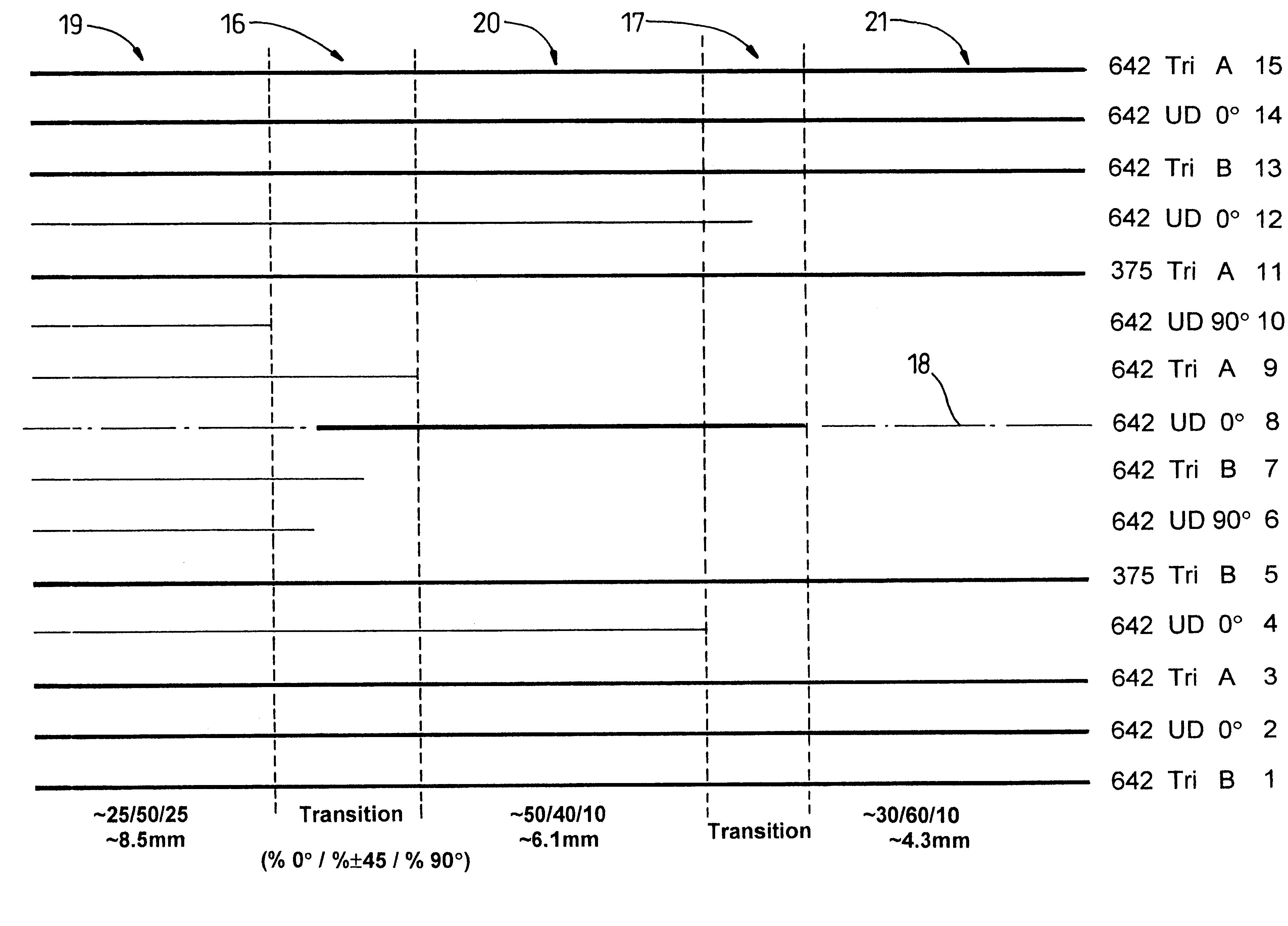
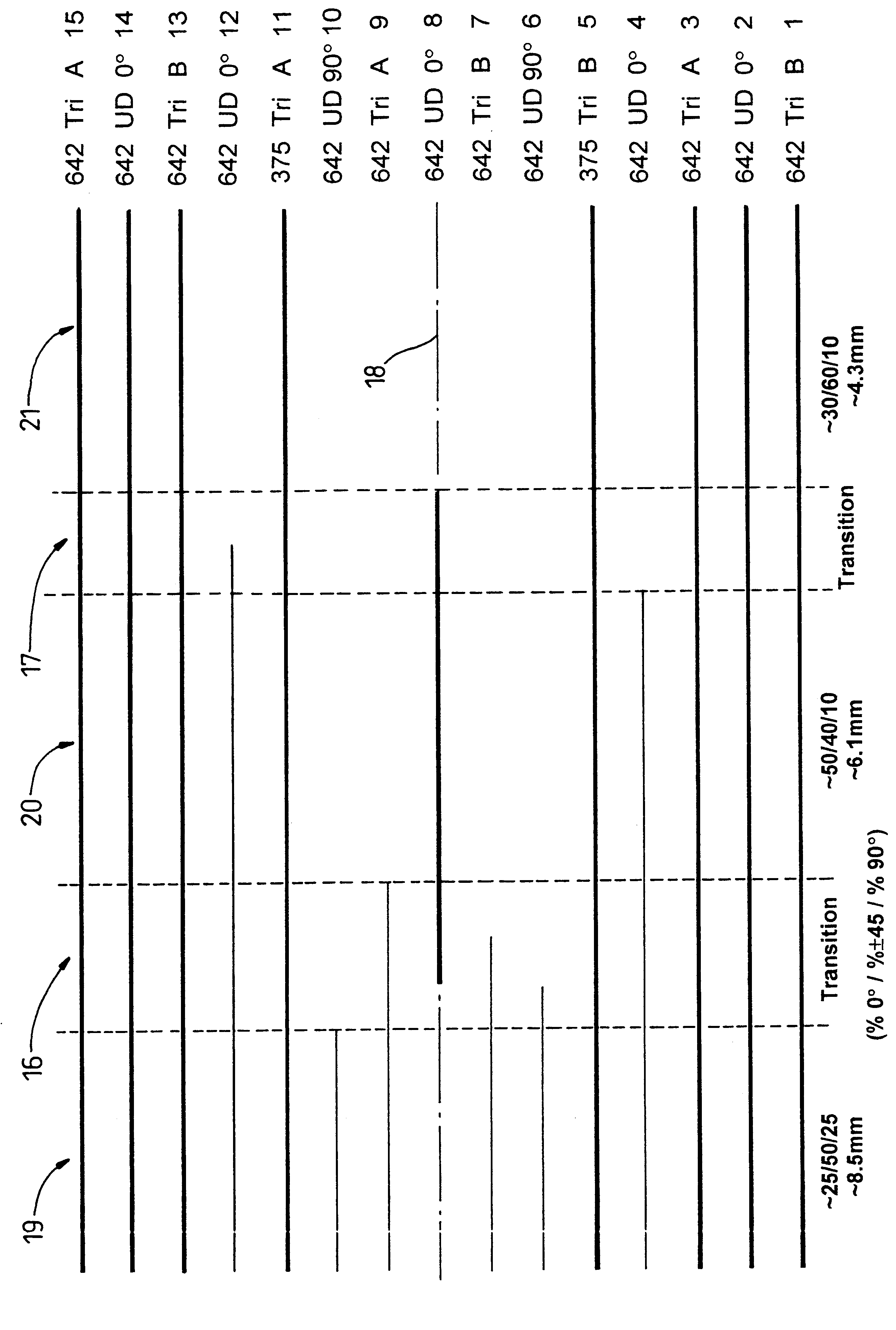
In the drawing layup optimization according to the invention has been utilized to create a layup whose fibre orientation ratio and thickness varies in the spanwise direction (NB in practice it would also vary in the chordwise direction.

The horizontal lines 1 to 15 each represent fabrics, with their areal weight in grams per square meter; type, ie Triaxial or Unidirectional; their handedness, A or B or whether 0 deg or 90 deg, and their consecutive number marked on the right hand side of the figure. It will be observed that fabrics 1, 2, 3, 5, 11, 13, 14 and 15 are continuous, whereas fabrics 4, 6, 7, 8, 9, 10, and 12 are discontinuous. It will also be observed that the latter fabrics all terminate within transition regions 16 and 17. Discontinuities of the fabrics are as far as possible confined to positions as close as

possible to the neutral axis 18 of the layup. Constant thickness regions 19, 20 and 21 have percentage fibre content ratios of 0 deg, plus or minus 45 deg and 90 deg ...


PUM

PropertyMeasurementUnit
thickaaaaaaaaaa
thicknessaaaaaaaaaa
degree of freedomaaaaaaaaaa

Abstract

A method of manufacturing a composite laminate and a composite laminate manufactured according to the method are provided. The laminate comprises a series of fabric plies (1 to 15) of fibrous reinforcing material set in plastics matrix material. The method includes the steps of providing a relatively small number of fabric styles from which to choose; selecting at least one of those fabric styles according to design requirements for a particular portion of the laminate; laying up that portion with the said selection, and repeating the selection and layup steps as required to complete the layup of the laminate.

Description

1. Field of the InventionThis invention relates to the design and manufacture of composite laminates, particularly fibre reinforced composite laminates, and more particularly to such laminates which are constructed from a series of plies of fabric, each ply being comprised of reinforcing fibres layed substantially in a single orientation. Such laminates find utility in the manufacture of highly stressed structures, for example in the manufacture of aircraft wings, where the ratio of strength and stiffness to weight is critical.2. Description of Prior ArtAn optimised aircraft wing, especially one made of carbon fibre based composite, is a very complex structure due to the variety of functions required of different types of wing component, eg. skins, stringers, ribs and spars. A potential advantage of composites over metals is that the strength and stiffness of the structure can be tailored by varying the percentage content of reinforcing fibre, the fibre orientation and sometimes the...

Claims


Application Information

Patent Timeline
Patent Type & Authority Patents(United States)
IPC IPC(8): B32B5/26B32B5/22B29B11/16B29K105/06B64C1/00B32B5/28B32B37/20B64C1/06B64C3/18
CPCB32B5/26Y10T156/1092Y10T442/3187B32B5/16B32B2305/07B32B2305/08B32B2605/18
Inventor HEALEY, MICHAEL J
Owner AIRBUS OPERATIONS LTD
Why Eureka
Try Eureka