
Composite stacking sequence optimization for multi-zoned composites

Active Publication Date: 2005-07-28
THE BOEING CO
View PDF18 Cites 45 Cited by
  • Summary
  • Abstract
  • Description
  • Claims
  • Application Information

AI Technical Summary

Benefits of technology

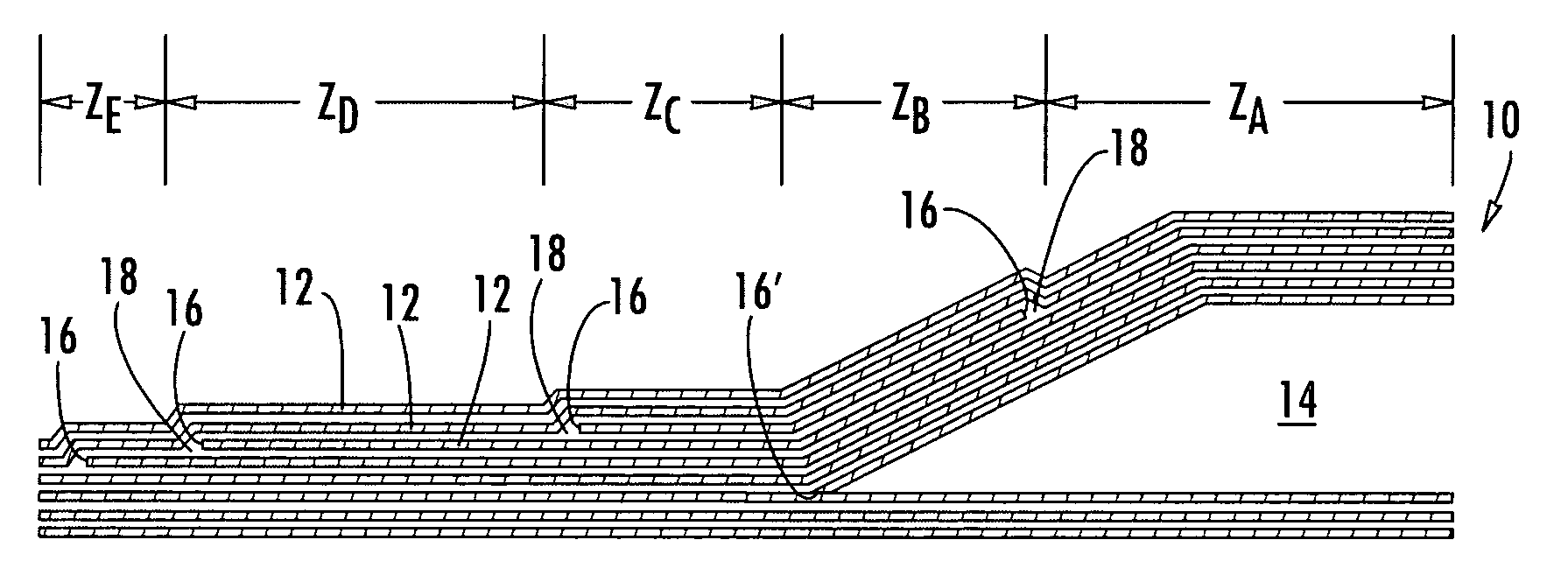
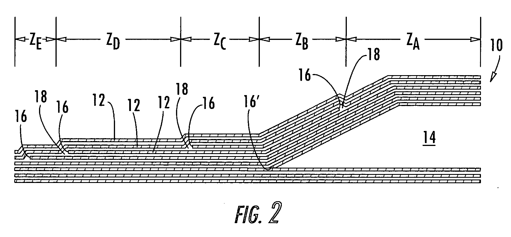
[0009] Further, the method, apparatus, and computer program product may provide a transformation matrix to correlate the plies of the master zone to the plies of each zone, wherein the transformation matrix is governed by the predefined series of design rules. Additionally, a weighted solid / void differential may be calculated for each zone to reduce the length or number of internal ply edges in the composite laminate by minimizing the weighted solid / void differential for each zone. Accordingly, by incorporating the transformation matrix and weighted solid / void differential when arranging the plies of each zone based upon the stacking sequence of the master zone, the method, apparatus, and computer program product of the present invention reduce the internal ply edges of the composite laminate with the most design rule compliant stacking sequence.

Problems solved by technology

However, the '511 patent does not discuss how to optimize a vertical stack of the plies based on structural rules such that the plies will be arranged for structural and cost considerations.
In addition, the '511 patent discloses heuristic-based methods of sequencing the plies of a composite laminate, which implement a predetermined suite of solution procedures specifically designed for a particular kind of composite part and which lack the flexibility of prioritizing different design rules in the solution procedure.
Poor placement of internal ply edges can increase the manufacturing costs for composite laminates having multiple zones.

Method used


Image

  • Composite stacking sequence optimization for multi-zoned composites
  • Composite stacking sequence optimization for multi-zoned composites
  • Composite stacking sequence optimization for multi-zoned composites

Examples


Embodiment Construction

[0022] The present invention now will be described more fully hereinafter with reference to the accompanying drawings, in which some, but not all embodiments of the invention are shown. Indeed, the invention may be embodied in many different forms and should not be construed as limited to the embodiments set forth herein; rather, these embodiments are provided so that this disclosure will satisfy applicable legal requirements. Like numbers refer to like elements throughout.

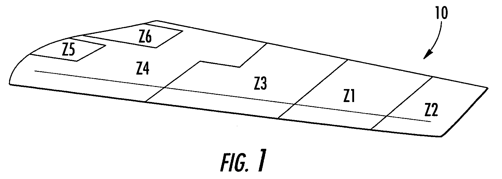
[0023] With reference to FIGS. 1-10, a method, apparatus, and computer program product in accordance with one embodiment of the present invention are provided. The method, apparatus, and computer program product of the present invention, also known as the Composite Stacking Sequence Optimizer (“CSSO”), reduce the internal ply edges in a composite laminate having two or more zones relative to comparable composite laminates that are stacked in accordance with conventional techniques. Zones are defined along the len...


PUM

PropertyMeasurementUnit
Lengthaaaaaaaaaa

Abstract

Method, apparatus, and computer program products are provided for optimizing a stacking sequence for a composite laminate having multiple zones to reduce the number or length of internal ply edges in the composite laminate with the most design rule compliant sequences. Once the number and location of the zones and the number of plies having different properties required for each zone have been determined for the composite laminate, a master zone is generated. Advantageously, the property of the plies may be fiber orientation, though alternative properties such as material may be considered when determining the number of required plies. The master zone notionally includes the maximum number of plies having a respective property required by any one zone, and the plies of the master zone are sequenced using a predefined series of design rules. The plies of each zone are then arranged based upon the stacking sequence of the master zone. A transformation matrix, a second predefined series of design rules, and a weighted solid / void differential may be used when arranging the plies of each zone based upon the stacking sequence of the master zone.

Description

BACKGROUND OF THE INVENTION [0001] 1. Field of the Invention [0002] The present invention is related to the design process of composite laminates, and more particularly, to a method for optimizing a stacking sequence for composite laminates with multiple zones having different numbers of plies. [0003] 2. Description of Related Art [0004] Composite laminates are structures created by laminating two or more plies together such that the cumulative properties of the composite laminate are superior to the individual properties of the plies. Composite laminates are commonly used throughout industry, particularly the aerospace industry, because of their engineering qualities, design flexibility, and low weight. The vertical, or “through the thickness,” arrangement, also called the stacking sequence, of the individual plies in the laminate is an important consideration in the design and manufacture of composite structures. Plies having a variety of properties, such as material and fiber ori...

Claims


Application Information

Patent Timeline
IPC IPC(8): B29C70/30B29C70/54
CPCB29C70/30Y10T428/24488Y10T428/24777B29C70/54G06F30/20G06F2113/24G06F2113/26G06F30/15G06F2111/04
Inventor CHEN, BING-CHUNGEASTLAND, CHRISTOPHER C.HANSON, CHRISTOPHER T.
Owner THE BOEING CO
Learn More