
Implement having rotational speed reduction and operating method therefor

a technology of rotational speed reduction and drive mechanism, which is applied in the direction of controlling members, limiting/preventing/returning movement of parts, and controlling members, etc., can solve the problems of uncombusted fuel discharge to the environment, coupling, and driven parts, and reduce the life of the engin

Inactive Publication Date: 2011-09-15
WACKER NEUSON SE
View PDF9 Cites 1 Cited by
  • Summary
  • Abstract
  • Description
  • Claims
  • Application Information

AI Technical Summary

Benefits of technology

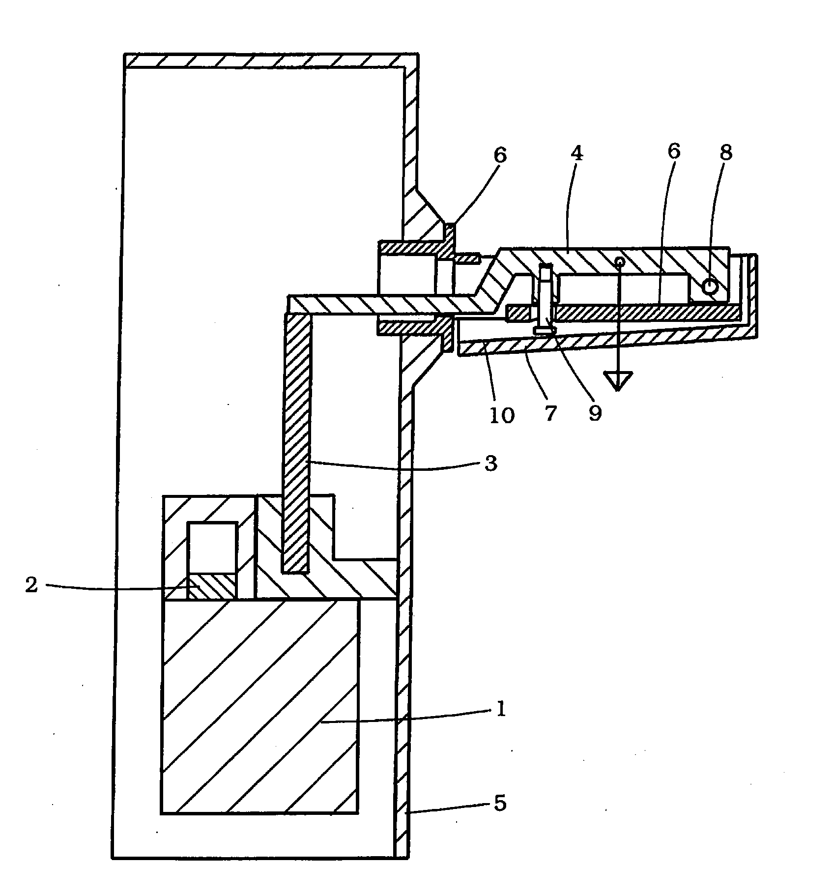
[0016]In this way, it can be achieved that by pressing down the holding device in the main operating direction while simultaneously actuating the gas actuating element, a full-load operation can be set, whereas solely by lifting the holding device (despite the fact that the gas actuating element continues to be actuated) the rotational speed control device, and therewith for example the throttle valve, is modified in such a way that for example a lower rotational speed is set in order to prevent the engine from increasing its rotational speed into the range of its maximum rotational speed.
[0020]In a first state, the gas actuating element is pressed forward in the main operating direction into its “second position,” and the holding device is also pressed in the main operating direction into its “second position.” Here, the gas actuating element assumes an extreme frontmost position, seen in the main operating direction. As a consequence, the rotational speed control device coupled to the gas actuating element, i.e. for example the throttle valve, assumes a full-load position, so that the internal combustion engine can be operated under full load.
[0024]The holding device can be pivotable relative to the bearer. In this way, a reliable and safe operation is ensured.

Problems solved by technology

To the extent that no control measures are implemented, the engine would rotate up to its maximum rotational speed, which ultimately would be limited only by the gas dynamic behavior inside the engine.
However, the achieving of the maximum rotational speed causes a reduction in the lifespan of the engine, the coupling, and the driven parts, as well as high vibrational loading and excessive noise.
In particular when there is a discontinuation of the ignition during individual operating cycles, uncombusted fuel is discharged to the environment through the exhaust.
If, due to exhaust gas regulations, a catalytic converter is provided in the exhaust system, the uncombusted fuel collects in the catalytic converter, which can cause overheating of the catalytic converter and ultimately its destruction.

Method used


Image

  • Implement having rotational speed reduction and operating method therefor
  • Implement having rotational speed reduction and operating method therefor
  • Implement having rotational speed reduction and operating method therefor

Examples


Embodiment Construction

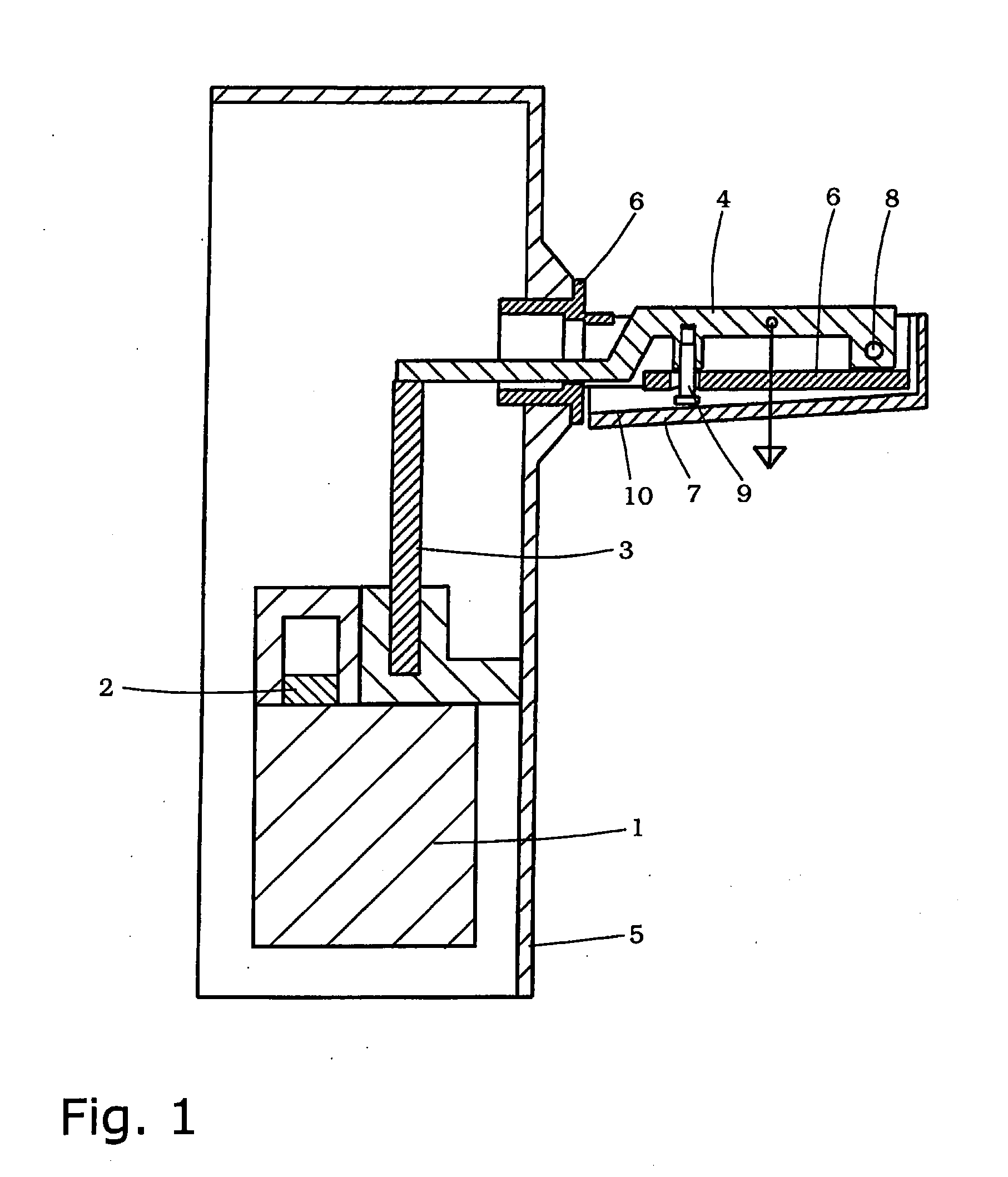
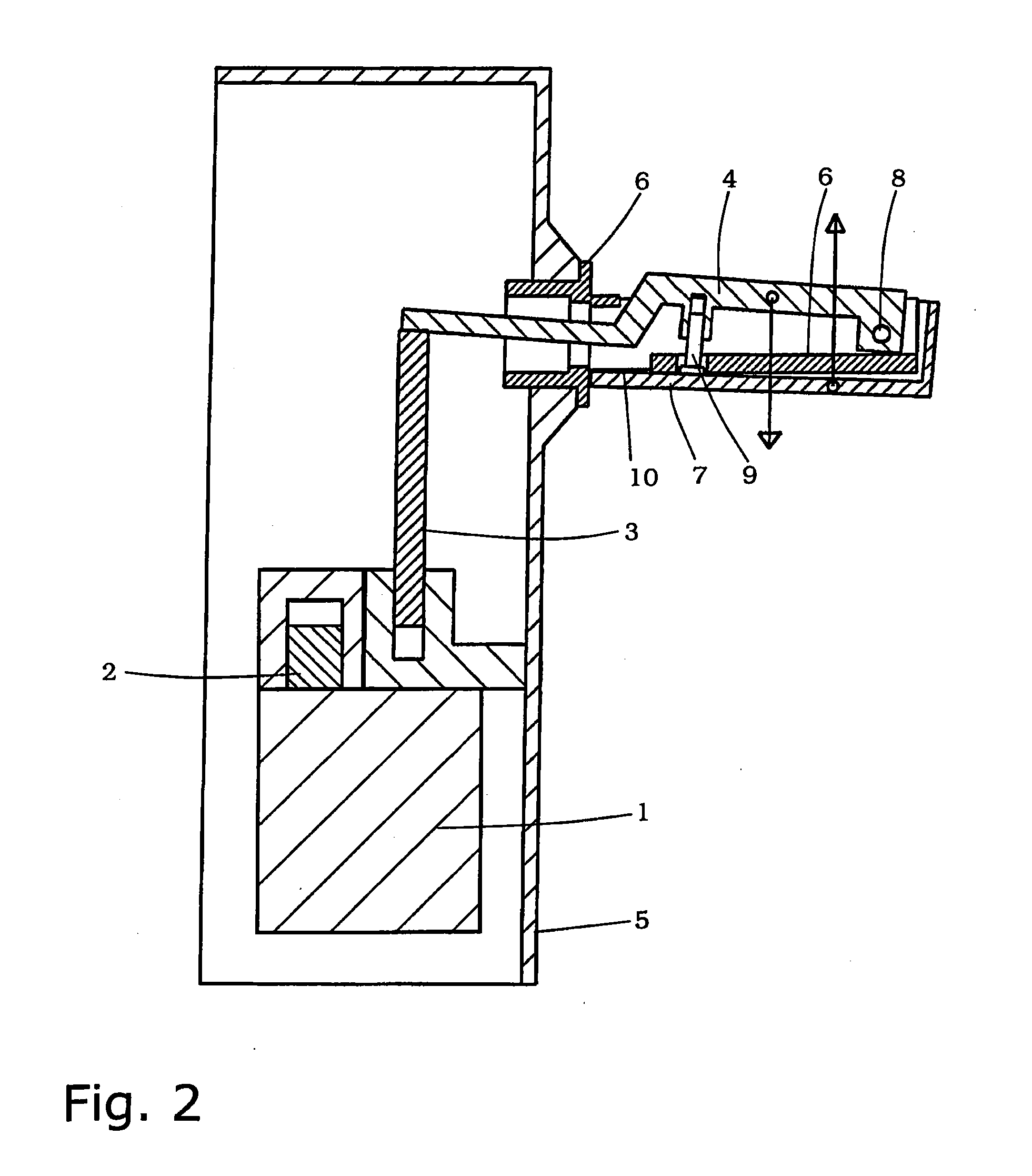
[0039]FIGS. 1 through 3 each show a schematic representation of a gasoline-operated breaking hammer, or a rail tamper, as an impact device, in a lateral sectional representation in various operating states. Parts of the device are shown only schematically.

[0040]The impact device is driven by an internal combustion engine 1, shown only symbolically, that charges an impact mechanism that is not shown. Internal combustion engine 1 has a rotational speed control device having a throttle valve 2. Throttle valve 2 is also shown only schematically. However, its functioning has long been known in the prior art, so that further description is unnecessary.

[0041]The position of throttle valve 2 can be adjusted between a fully open position, corresponding to a full-load or full-gas operating mode (FIG. 1) through a part-load position (partly open, FIG. 2) to a no-load position (largely closed, FIG. 3).

[0042]The adjustment of throttle valve 2 takes place using a rod or Bowden cable 3 that transm...


PUM


Abstract

An implement comprises an internal combustion engine having a throttle valve. At least one handle, the inside of which is provided with a gas lever likewise in a pivotal manner, is attached to a housing surrounding the internal combustion engine. The minimum distance between the gas lever and the handle is defined by a stop. When the operator lifts the implement by the handle, the position of the gas lever also changes. Even when the gas lever is fully depressed, only a part-load position is achieved at the throttle valve. In this way, effective rotational speed limitation is achieved.

Description

BACKGROUND OF THE INVENTION[0001]1. Field of the Invention[0002]The present invention relates to an implement driven by an internal combustion engine, such as an impact device, in particular a drilling or breaking hammer, a tamper, or some other device in which the operator must cause a force to act in a defined direction. In addition, the present invention relates to an operating method for such an implement.[0003]2. Description of the Related Art[0004]Impact devices often have a gasoline-powered internal combustion engine that drives an impact mechanism. The impact effect is transmitted to a corresponding tool in order to achieve the desired operational effect. Impact devices are predominantly used in two rotational speed ranges; a distinction is made between no-load operation and full-load operation. Full-load operation corresponds to the operating mode in which the device operates in the intended manner.[0005]The operating mode of the internal combustion engine, and thus the dis...

Claims


Application Information

Patent Timeline
IPC IPC(8): F02D39/00
CPCB25D9/10B25D9/26B25D9/265B25D17/04G05G5/04B25D2250/245F02D11/00G05G1/04B25D2250/005
Inventor HAUSLER, WOLFGANGBRAUN, HELMUT
Owner WACKER NEUSON SE
Learn More