Method and Materials for Proppant Flow Control With Telescoping Flow Conduit Technology

a technology of telescopic flow conduit and proppant flow, which is applied in the direction of wellbore/well accessories, fluid removal, sealing/packing, etc., can solve the problems of system not providing a filter structure, formation fluids, and devices obstructing or preventing high-viscosity fluids and proppants utilized in hydraulic fracturing. to achieve the effect of inhibiting or preventing flow

Active Publication Date: 2011-09-15
BAKER HUGHES INC
View PDF11 Cites 44 Cited by
  • Summary
  • Abstract
  • Description
  • Claims
  • Application Information

AI Technical Summary

Benefits of technology

There is provided, in one non-limiting form, a method for extracting well fluids from a fractured hydrocarbon formation while controlling the flow of proppant back through the wellbore. The hydrocarbon formation has disposed within it a pipe having orifices through at least a region of its wall, and telescoping flow conduits, pathways, channels, passages, outlets, or the like situated within the orifices in a retracted position within the pipe. The telescoping flow conduits contain porous objects disposed within them to control the flow of proppant and sand from the formation. The hydraulic fracturing method includes extending the telescoping flow conduits radially outward from the pipe in the direction of the wellbore wall via an extension fluid. Hydraulic fracturing fluid may then be injected into the subterranean reservoir via the pipe and the telescoping flow conduits. The porous objects are then injected into the telescoping flow conduits to control the flow of proppant...

Problems solved by technology

However, filters in the above-described TELEPERF™ devices may obstruct or impede the high-viscosity fluids and proppants utilized in hydraulic fracturing from entering the formation.
Although the TELEFR...

Method used


Image

  • Method and Materials for Proppant Flow Control With Telescoping Flow Conduit Technology
  • Method and Materials for Proppant Flow Control With Telescoping Flow Conduit Technology
  • Method and Materials for Proppant Flow Control With Telescoping Flow Conduit Technology

Examples


Embodiment Construction

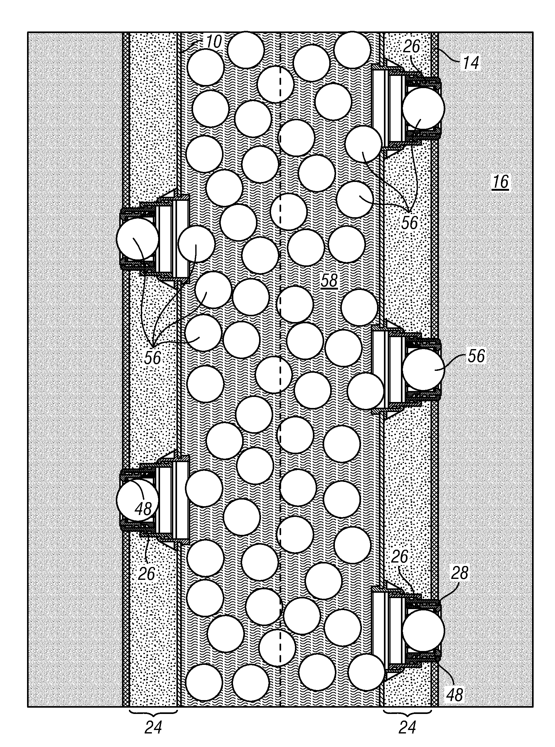
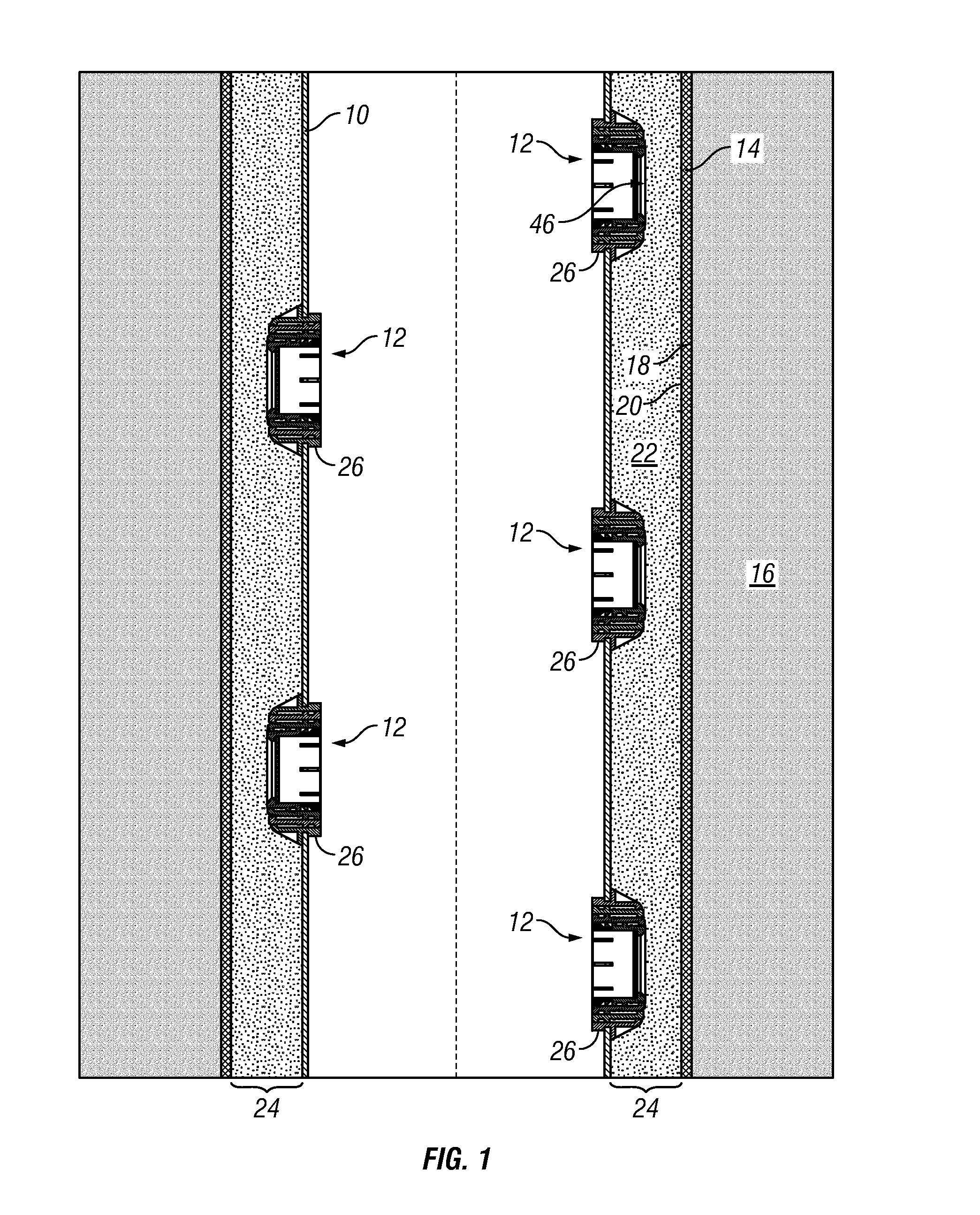
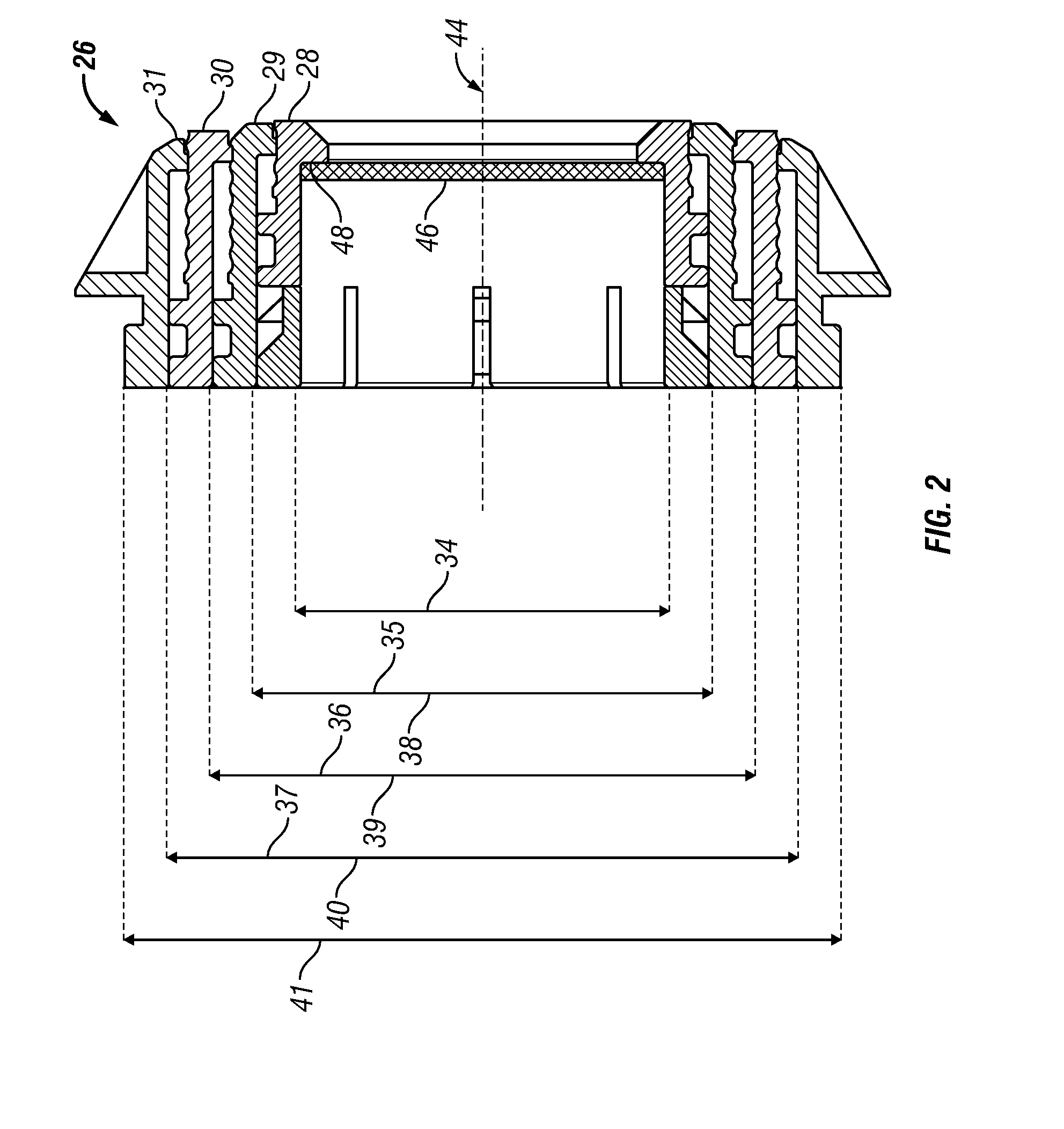
In accordance with a present embodiment, an oil well casing or liner may contain pre-formed perforations, or holes, therethrough. Further, installed in each perforation may be a moveable fluid conduit or pathway which enables fluid communication between the interior and the exterior of the casing or liner. For example, the fluid conduit may be several generally cylindrical conduits arranged coaxially with a limited range of motion relative to each other along the commonly shared axis, e.g. in a telescoping configuration.

The flow conduits or pathways may further contain temporary plugs which inhibit or prevent the flow of fluid through the conduits. The moveable flow conduits or pathways may be telescoped out from the casing or liner into the wellbore annulus via fluid pressure within the casing or liner. That is, as fluid is pumped into the casing, the temporary plugs inhibit the fluid from exiting the casing via the flow conduits. Rather, as the pressure inside the casing increases...


PUM


Abstract

Porous objects, such as porous balls, may be employed within telescoping devices to control proppant flowback through a completed well during production. The telescoping devices may connect a reservoir face to a production liner without perforating. Acid-soluble plugs initially disposed within the telescoping devices may provide enough resistance to enable the telescoping devices to extend out from the production liner under hydraulic pressure. The plugs may then be dissolved in an acidic solution, which may also be used as the hydraulic extension fluid. After the plugs are substantially removed from the telescoping devices, the reservoir may be hydraulically fractured using standard fracturing processes. The porous balls may then be inserted into the telescoping devices to block proppant used in the fracturing process from flowing out of the reservoir with the production fluids.

Description

TECHNICAL FIELDThe present invention relates to methods and compositions for controlling proppant flow through a wellbore, and more particularly relates, in one embodiment, to methods and compositions for controlling proppant flow through a wellbore after proppant fracturing.BACKGROUNDThere are a number of procedures and applications that involve the formation of a temporary seal or plug while other steps or processes are performed, where the seal or plug must be later removed. Often such seals or plugs are provided to temporarily block a flow pathway or inhibit the movement of fluids or other materials, such as flowable particulates, in a particular direction for a short period of time, when later movement or flow is desirable.The recovery of hydrocarbons from subterranean formations often involves applications and / or procedures employing coatings or plugs. In instances where operations must be conducted at remote locations, namely deep within the earth, equipment and materials can...

Claims


Application Information

Patent Timeline
IPC IPC(8): E21B43/26E21B33/12
CPCE21B23/04E21B43/267E21B34/063E21B23/0413
Inventor HUANG, TIANPINGXU, RICHARD YINGQING
Owner BAKER HUGHES INC
Why Eureka
Try Eureka