Disc brake backing plate and methods of manufacturing the same

Inactive Publication Date: 2011-09-15
ZHANG JIM ZEWEI
View PDF11 Cites 20 Cited by
  • Summary
  • Abstract
  • Description
  • Claims
  • Application Information

AI Technical Summary

Benefits of technology

[0006]The present invention uses multiple recesses (2) on the backing plate to increase the adhesion between the backing plate and the friction material, and thus increase the shearing strength of th

Problems solved by technology

The challenge in this area is to increase the adhesion between the backing plate and the friction material while neither dec

Method used


Image

  • Disc brake backing plate and methods of manufacturing the same
  • Disc brake backing plate and methods of manufacturing the same

Examples


Embodiment Construction

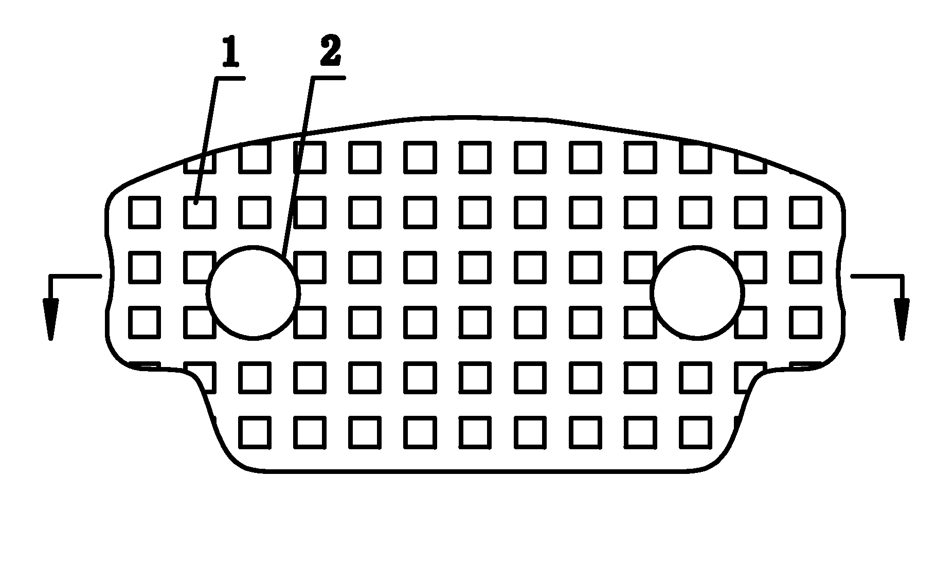
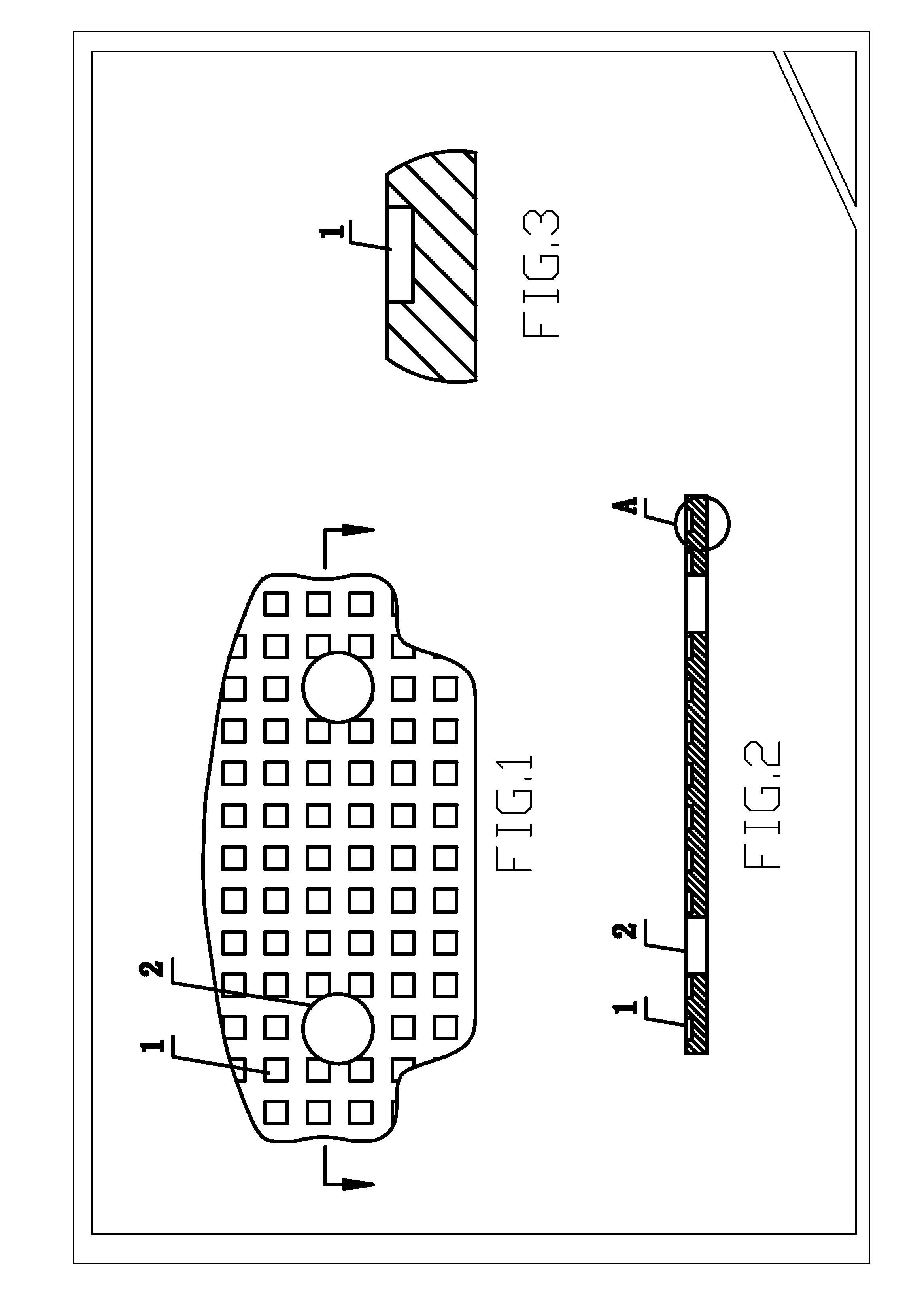
[0011]This present invention places a matrix of recesses (2) onto the backing plate therefore increasing the ability to withstand shearing force between the backing plate and the friction material by (i) increased surface area and (ii) the creation of engagement, i.e., friction locking, between the recesses (2) in the backing plate and the corresponding protrusions on the friction material.

[0012]The placement and size of the recesses (2) is critical in enhancing the adhesion, which is measured by (i) the retention area and (ii) the shearing strength.

[0013]The retention area is defined as the area where the friction material that remains on the backing plate after a shearing force is applied on the friction material enough to cause the friction material to break away from the backing plate.

[0014]The shearing strength is defined as the maximum shear stress that the joint between the backing plate and the friction material can withstand without rupture.

[0015]When the recess area is gre...


PUM

PropertyMeasurementUnit
Areaaaaaaaaaaa
Areaaaaaaaaaaa
Depthaaaaaaaaaa

Abstract

A disc brake pad is composed of a backing plate and a friction material. The adhesion of the backing plate and the friction material is enhanced in the present invention by multiple recesses on the surface of the backing plate that is attached to the friction material. One of the advantages of the present invention is the ease of manufacturing. In one of the preferred methods of manufacturing, a matrix of recesses (2) is first impressed onto the steel sheet by a stamping press. The existing method of producing a traditional backing plate, i.e., stamping out the backing plate profile and the bores, may then be applied.

Description

[0001]This application claims the benefit of Chinese Patent Application No. 200810197495.6, filed on Oct. 31, 2008, which is relied upon and incorporated by reference herein.FIELD OF INVENTION[0002]The present invention concerns a novel backing plate of a brake pad of a disc brake to enhance the adhesion between the backing plate and the friction material.BACKGROUND OF THE INVENTION[0003]When a disc brake is applied, the caliper pushes the friction material against the rotor via the backing plate. In reference to the car, the friction that the rotor applied to the friction material is in the direction of the motion of the rotor. The caliper applies a force of the same magnitude but in the opposite direction on the backing plate to keep the brake pad stationary. The adhesion between the backing plate and the friction material must sustain the shearing force caused by the friction on the friction material and the caliper on the backing plate.DESCRIPTION OF RELATED ART[0004]There have ...

Claims


Application Information

Patent Timeline
IPC IPC(8): F16D65/04B23P11/00
CPCF16D65/092F16D69/0408Y10T29/49826F16D2250/00F16D2069/0441
Inventor ZHANG, JIM ZEWEI
Owner ZHANG JIM ZEWEI
Why Eureka
Try Eureka