Piezoelectric vibrating pieces and piezoelectric devices comprising same

Inactive Publication Date: 2011-09-15
NIHON DEMPA KOGYO CO LTD
View PDF14 Cites 15 Cited by
  • Summary
  • Abstract
  • Description
  • Claims
  • Application Information

AI Technical Summary

Benefits of technology

[0006]The present invention addresses the foregoing issues and provides, inter alia, piezoelectric vibrating pieces and piezoelectric devices comprising same, in which the electric field is not reduced despite miniaturization and that allow volume manufacturing and stability of vibration.

Problems solved by technology

I.e., as the tuning-fork type piezoelectric vibrating piece is reduced in size, the produced vibrations become less stable.
As a result, it is increasingly difficult to form a pair of grooves in the space between the vibrating-arm grooves of the tuning-fork type piezoelectric vibrating piece disclosed in the '743 reference, and it is also increasingly difficult to form excitation electrodes between the vibrating arms.
Also, since four grooves are formed between the vibrating arms, the strength of the base is reduced, which may adversely affect stability and / or reliability of vibration.

Method used


Image

  • Piezoelectric vibrating pieces and piezoelectric devices comprising same
  • Piezoelectric vibrating pieces and piezoelectric devices comprising same
  • Piezoelectric vibrating pieces and piezoelectric devices comprising same

Examples


fourth embodiment

of a Tuning-Fork Type Piezoelectric Vibrating Piece

[0068]A tuning-fork type piezoelectric vibrating piece 10D of this embodiment is described below with reference to FIG. 6, which is a plan view. In this embodiment, components that are similar to corresponding components in the first embodiment have the same respective reference numerals.

[0069]In FIG. 6 each vibrating arm defines two groove portions on each main surface thereof. In other words, in this embodiment each vibrating-arm groove that is entire in the first embodiment is divided. Specifically, the first vibrating-arm groove 13A on the left-hand vibrating arm 22 is divided into two excitation-groove portions 13Aa, 13Ab, and the second vibrating-arm groove 13B on the right-hand vibrating arm 22 is divided into two excitation-groove portions 13Ba, 13Bb. The same configuration of divided grooves is also present on the lower main surface of the vibrating arms 22. Dividing the vibrating-arm grooves in this manner enhances the str...

fifth embodiment

of a Tuning-Fork Type Piezoelectric Vibrating Piece

[0071]This embodiment of a piezoelectric vibrating piece 10E is described below with reference to FIG. 7, which is a plan view. In FIG. 7 components that are similar to corresponding components in the first embodiment have the same respective reference numerals.

[0072]In FIG. 7, each vibrating arm 32 includes a respective vibrating-arm groove 13A, 13B on each main surface thereof. Each groove 13A, 13B extends onto the base 41, which can reduce the strength of the vibrating arms 32. To prevent this strength reduction, the root portions 321 of each vibrating arm are wider toward the base 41. As a result, the vibrating arms 32 vibrate stably, and the reliability of this embodiment 10E is not compromised by the grooves.

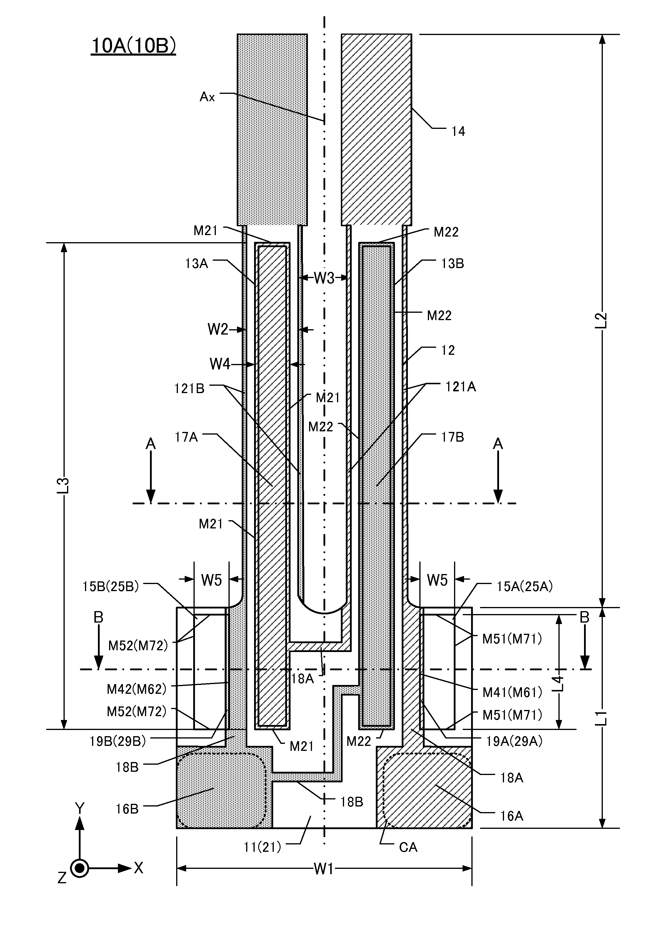
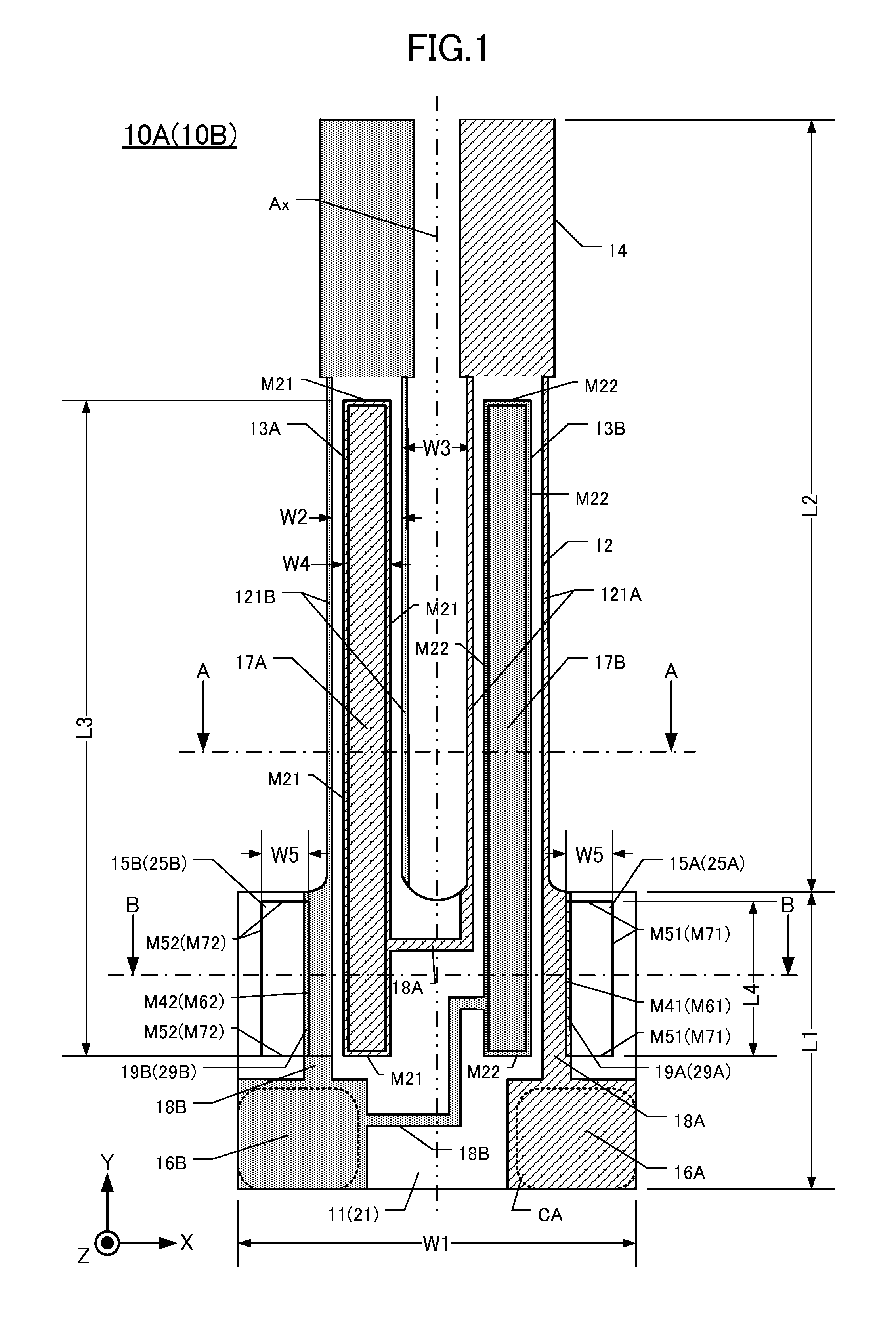
[0073]By way of example, the width W2 in the X-axis direction of each vibrating arm near its respective weight 14 is about 80 to 120 μm. The distance W3 between the vibrating arms 32 at this location is about 100 μm. The w...

sixth embodiment

of a Tuning-Fork Type Piezoelectric Vibrating Piece

[0074]This embodiment of a piezoelectric vibrating piece 10F it is described below with reference to FIG. 8, which is a plan view. In FIG. 8 components that are similar to corresponding components in the first embodiment have the same respective reference numerals.

[0075]In FIG. 8, the vibrating-arm groove 13A defined in the upper main surface of the left-hand vibrating arm 42 is divided into two excitation-groove portions 13Aa, 13Ab. Similarly, the vibrating-arm groove 13B defined in the upper main surface of the right-hand vibrating arm is divided into two excitation-groove portions 13Ba, 13Bb. Similar divisions of the vibrating-arm grooves are present on the lower main surface. This configuration enhances the strength of the vibrating arms, prevents increases in equivalent series resistance, and reduces stress at vibration flection points.

[0076]The vibrating-arm groove portions 13Ab, 13Bb extend well into the base 51, which can re...


PUM


Abstract

An exemplary tuning-fork type piezoelectric vibrating piece has a rectangular base having upper and lower main surfaces and a pair of vibrating arms extending longitudinally from the base. The vibrating arms also have the upper and lower main surfaces. Each main surface of each vibrating arm defines a respective vibrating-arm groove extending longitudinally into the base. Each main surface of the base has at least one respective step-side surface situated outboard, in an X-axis direction, of each vibrating-arm groove. Each step-side surface is parallel with the respective vibrating-arm groove. A first electrode is situated on the vibrating-arm grooves of the first vibrating arm and on the at least one respective step-side surface on each main surface. A second electrode is situated on the vibrating-arm grooves of the second vibrating arm and on the at least one respective step-side surface on each main surface. The first and second electrodes are energized with different electrical polarities.

Description

CROSS-REFERENCE TO RELATED APPLICATIONS[0001]This application claims priority to and the benefit of Japan Patent Application No. 2010-057253, filed on Mar. 15, 2010, and Japan Patent Application No. 2010-069447, filed on Mar. 25, 2010, in the Japan Patent Office, the disclosures of which are incorporated herein by reference in their respective entireties.FIELD[0002]This disclosure relates to, inter alia, tuning-fork type piezoelectric vibrating pieces made of a crystal material and a piezoelectric crystal material, such as lithium niobate. The disclosure also pertains to piezoelectric devices including such pieces.DESCRIPTION OF THE RELATED ART[0003]Tuning-fork type piezoelectric vibrating pieces having a base and a pair of vibrating arms extending from the base are known. The smaller the tuning-fork type piezoelectric vibrating piece, the smaller the electrical field component generated by the vibrating arms, and the larger the equivalent series resistance. Thus, a small tuning-for...

Claims


Application Information

Patent Timeline
IPC IPC(8): H01L41/08H01L41/04
CPCH03H9/0207H03H9/0519H03H9/21H03H9/1035H03H9/1021
Inventor IWAI, HIROKI
Owner NIHON DEMPA KOGYO CO LTD
Why Eureka
Try Eureka