Printing device and printing method

a printing device and printing method technology, applied in the direction of lithography, duplicating/marking methods, coatings, etc., can solve the problems of lack of consideration in the printing technique, and lack of consideration in the printing method in a manner, so as to preserve the gloss effect, preserve the color saturation of color printing, and preserve the effect of good saturation

Active Publication Date: 2011-09-15
SEIKO EPSON CORP
View PDF12 Cites 26 Cited by
  • Summary
  • Abstract
  • Description
  • Claims
  • Application Information

AI Technical Summary

Benefits of technology

[0012]According to the second aspect, the dye-based ink penetrates to the lower layer side of the light-blocking layer which is formed by the specialty gloss ink (herein also termed the “special gloss layer”), where it produces color. If the printed translucent printing medium is viewed from the back face side of the printed face, the first color-producing layer of dye based color ink that has penetrated into the printing medium is seen to overlap the special gloss layer printed with specialty gloss ink. The first color-producing layer which overlaps the special gloss layer printed with specialty gloss ink produces the color of the dye based color ink with good saturation; and because dye based color inks are highly translucent, the effect of the special gloss area situated on the lower layer side does not suffer. As a result, it is possible both to preserve the gloss effect and to preserve the color saturation of color printing in an image printed concomitantly with specialty gloss ink and dye based color ink. Further, the printed result afforded by the second color-producing layer may be ascertained by viewing the printed translucent printing medium from the printed face. That is, color images having gloss effect may be obtained on both faces of the translucent printing medium.
[0023]According to the third aspect, an effect comparable to the aforementioned second aspect may be achieved in relation to viewing a printed translucent printing medium from the back face side of the printed face.
[0025]According to the fourth aspect, an effect comparable to the aforementioned second aspect may be achieved in relation to viewing a printed translucent printing medium from the printed face side.A printing device according to a fifth aspect is the printing device according to the fourth aspect, further including a selection portion providing an interface allowing selection of one of the first, second and third printing modes when printing is executed. The printing control portion is preferably configured to execute printing according to the one of the first, second and third printing modes selected by the selection portion.
[0030]According to the seventh aspect, formation of the light-blocking layer and formation of the first color-producing layer are carried out concomitantly during a single pass of travel by the serial head, whereby the time required for printing can be shorter.

Problems solved by technology

However, the technique lacks sufficient consideration in relation to printing with specifically focus upon the type of inks used as the color inks and the qualities thereof.
Nor is sufficient consideration given to printing in a manner that utilizes the features of a translucent printing medium.

Method used


Image

  • Printing device and printing method
  • Printing device and printing method
  • Printing device and printing method

Examples


modified example 1

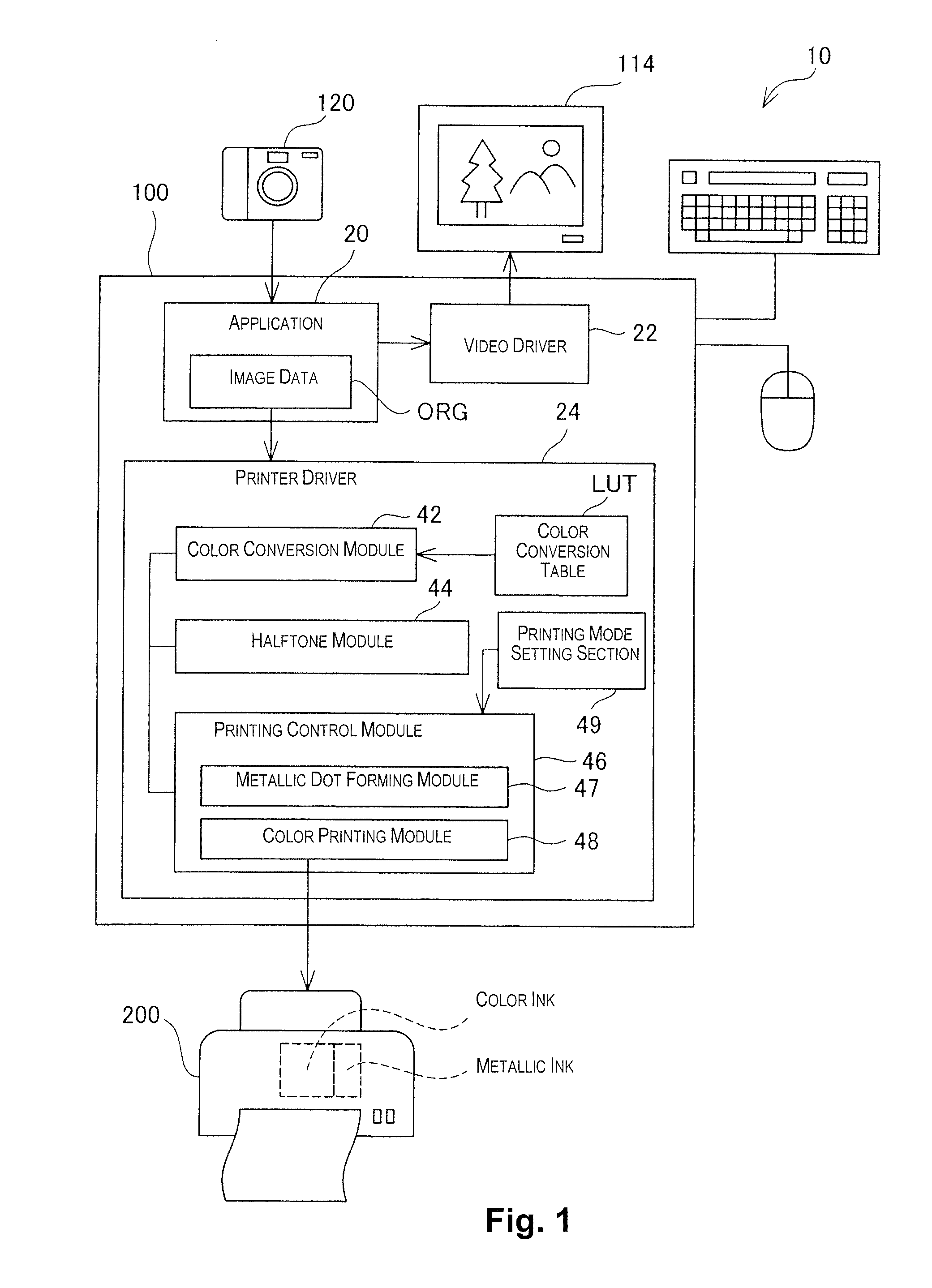
[0110]In the preceding embodiments, printing with metallic ink is carried out by the printing system 10 which includes the computer 100 and the printer 200. However, optionally, the printer 200 itself may input image data from a digital camera or memory card of any of various formats, and print the image with metallic ink. That is, the CPU in the control circuit 260 of the printer 200 may carry out printing with metallic ink through execution of a process comparable to the printing process in the embodiments described above.

modified example 2

[0111]Whereas the preceding embodiments describe examples in which the specialty gloss ink is metallic ink, pearlescent gloss inks containing pigments that have a pearlescent gloss effect once fixed onto the surface of a medium, for example, a pigment containing multiple stacked thin layers having a pearl color like natural pearl, or lame inks or translucent inks containing pigments that have microscopic irregularities so as to give rise to scattered reflection once fixed onto the surface of a medium to create a so-called lame or translucent effect, may be used in place of metallic ink. Optionally, an opaque white ink may be used in place of metallic ink. The white ink may be one containing hollow resin particles as coloring material, for example.

modified example 3

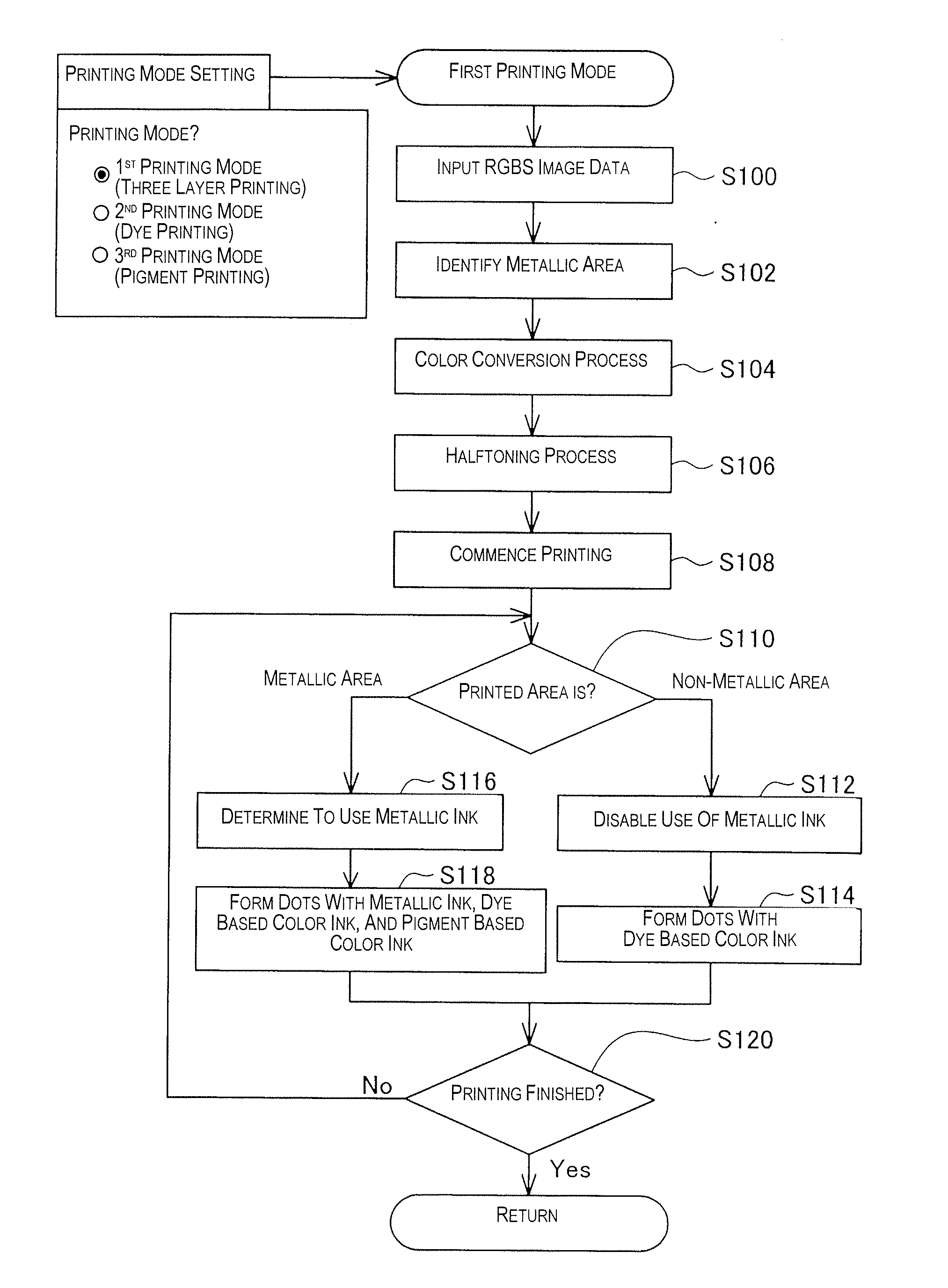
[0112]In the first printing mode described in the preceding embodiment, the pigment based color producing area CA2 is formed over the metallic area MA; however, dye based color ink may be printed over the metallic area MA to form a color producing area instead. During this process, optionally, a clear layer for inhibiting penetration of the dye-based ink into the metallic area MA may be formed over the metallic area MA. Optionally, a three-layer metallic / color area may be formed by printing of pigment based color ink, metallic ink, and pigment based color ink in that order. That is, color materials having identical qualities may used to either side of the metallic area MA.


PUM

PropertyMeasurementUnit
equivalent circle diameteraaaaaaaaaa
viscosityaaaaaaaaaa
thicknessaaaaaaaaaa

Abstract

The printing device for carrying out printing on a translucent printing medium includes: a print head having a first applying portion for applying a first color material onto the printing medium, a second applying portion for applying a second color material, and a third applying portion for applying an opaque specialty ink; a conveying portion for conveying the printing medium relative to the print head; and a printing control portion configured to execute printing according to a printing mode in which a first color-producing layer of the first color material is formed on the conveying printing medium using the first applying portion, an opaque light-blocking layer of the specialty ink is formed using the third applying portion, and a second color-producing layer of the second color material is formed over the light-blocking layer using the second applying portion after the light-blocking layer is formed.

Description

CROSS-REFERENCE TO RELATED APPLICATIONS[0001]This application claims priority to Japanese Patent Application No. 2010-052598 filed on Mar. 10, 2010. The entire disclosure of Japanese Patent Application No. 2010-052598 is hereby incorporated herein by reference.BACKGROUND[0002]1. Technical Field[0003]The present invention relates to a printing device and to a printing method.[0004]2. Related Art[0005]Techniques known in the past for carrying out printing using specialty inks in addition to color inks include, for example, the technique disclosed in Japanese Laid-Open Patent Application Publication No. 2007-50555.[0006]This technique is intended to prevent color mixing between white ink and color inks, in instances where white ink is used as a specialty ink. However, the technique lacks sufficient consideration in relation to printing with specifically focus upon the type of inks used as the color inks and the qualities thereof. Nor is sufficient consideration given to printing in a m...

Claims


Application Information

Patent Timeline
Patent Type & Authority Applications(United States)
IPC IPC(8): B41J29/38B05D5/00
CPCB41C2210/14B41J2/2107B41J3/407B41M5/0047B41M5/0064B41M5/502B41J2/04541B41J2/0458
Inventor YOSHIDA, SEISHINSANO, TSUYOSHIKAGATA, TAKAYOSHI
Owner SEIKO EPSON CORP
Why Eureka
Try Eureka