
Image pickup apparatus and its control method

a technology of image pickup and touch panel, which is applied in the field of image pickup apparatus, can solve the problems of difficult to realize an image pickup apparatus by using a general low-cost touch panel, and the occurrence of camera shaking rises, and achieves the effect of high operability

Inactive Publication Date: 2011-09-15
CANON KK
View PDF14 Cites 41 Cited by
  • Summary
  • Abstract
  • Description
  • Claims
  • Application Information

AI Technical Summary

Benefits of technology

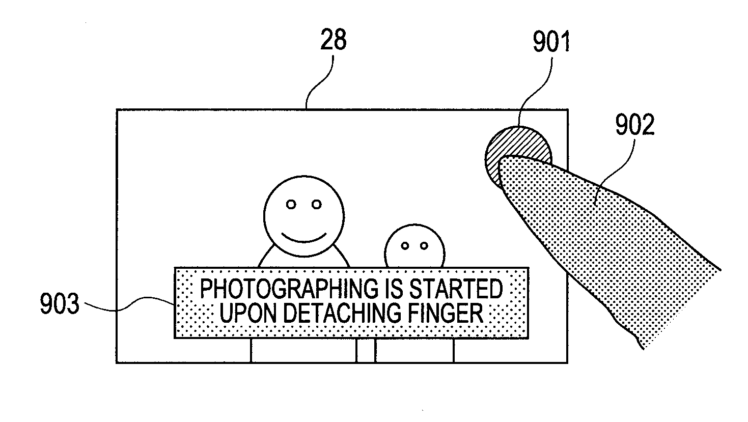
[0013]It is desirable to provide an image pickup apparatus which can solve the foregoing problems of the related arts and realize a photographic preparation operation instruction and a photographic instruction by a touch operation which can attain high operability while avoiding that a camera is shaken due to the touch operation.
[0015]The photographic preparation operation instruction and the photographic instruction can thus be made by the touch operation of high operability while avoiding that the camera is shaken due to the touch operation.

Problems solved by technology

Although the methods of attaining the states SW1 and SW2 of the release switch using the touch detection unit have existed hitherto as mentioned above, a problem still remains in any of the above related arts and a countermeasure for solving such a problem is demanded.
For instance, in the example using the touch panel which is arranged to detect the pressure or the touch area of the finger pressing, it is necessary to strongly press the liquid crystal screen to attain the full depression SW2 state of the release switch, so that there is such a problem that a possibility of occurrence of the camera shaking rises.
In addition, since the touch panel which is arranged to detect the pressure or the touch area of the finger pressing is necessary, it is difficult to realize an image pickup apparatus by using a general low-cost touch panel which outputs only touch coordinates.
The touch panel is thus difficult and costly to manufacture.
Further, since the example using the two touch sensors requires the two sensor devices, this may be a factor of causing an increase in costs and also results in such a problem that an operation procedure is complicated and is hard to be learned, and it is also difficult to operate with one hand.

Method used


Image

  • Image pickup apparatus and its control method
  • Image pickup apparatus and its control method
  • Image pickup apparatus and its control method

Examples


first embodiment

[0045]In the first embodiment, an example will be described in which the photographic preparation operation is executed by a user performing “touch-down” onto the shutter icon displayed on the touch panel and, thereafter, the photographing process is executed by performing “touch-up” on the shutter icon.

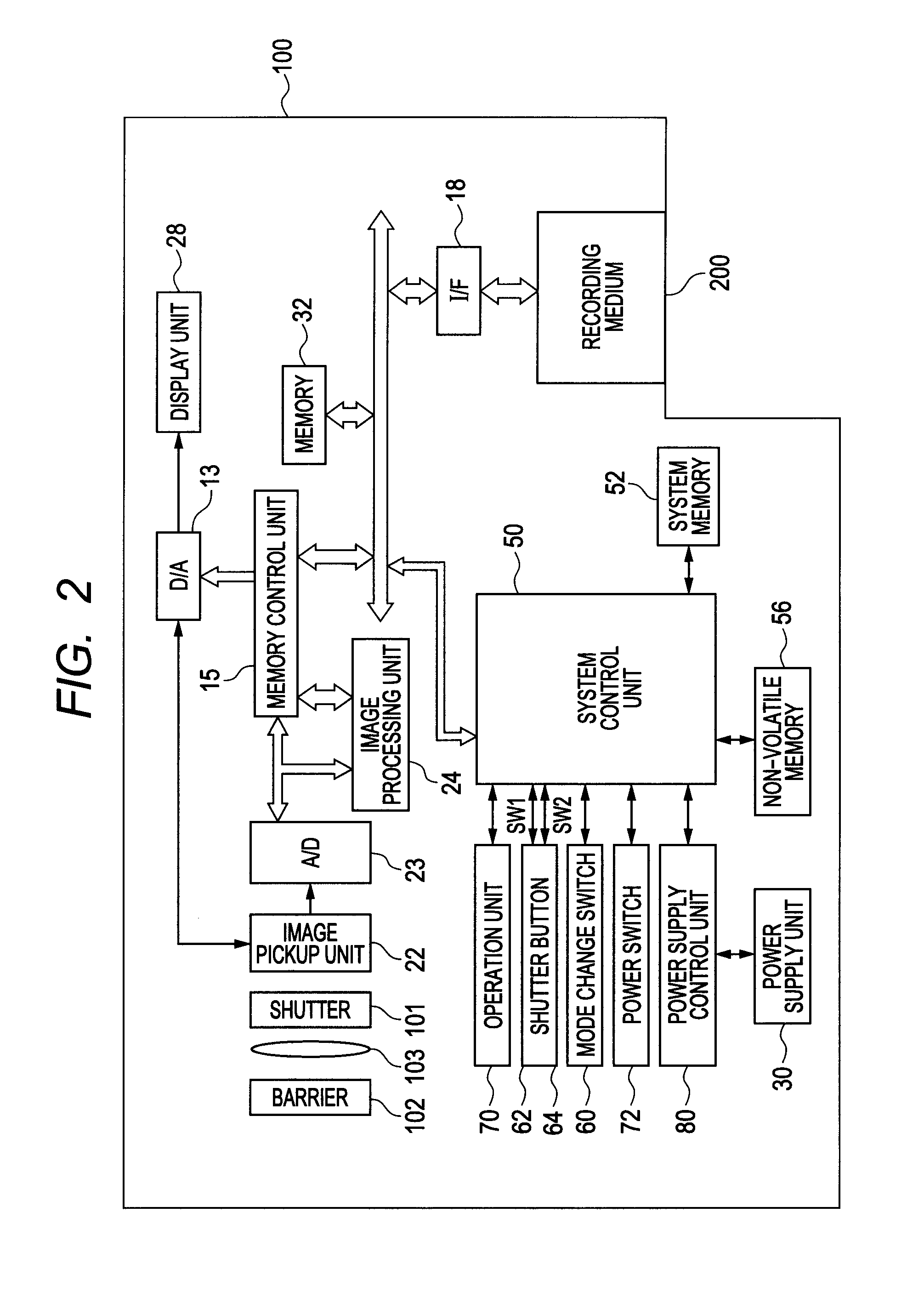
[0046]FIG. 3 illustrates a flowchart for a photographic mode process 1 as a process in the photographic mode of the first embodiment. The photographic mode process 1 is realized by a method whereby the system control unit 50 develops the program recorded in the non-volatile memory 56 into the system memory 52 and executes it.

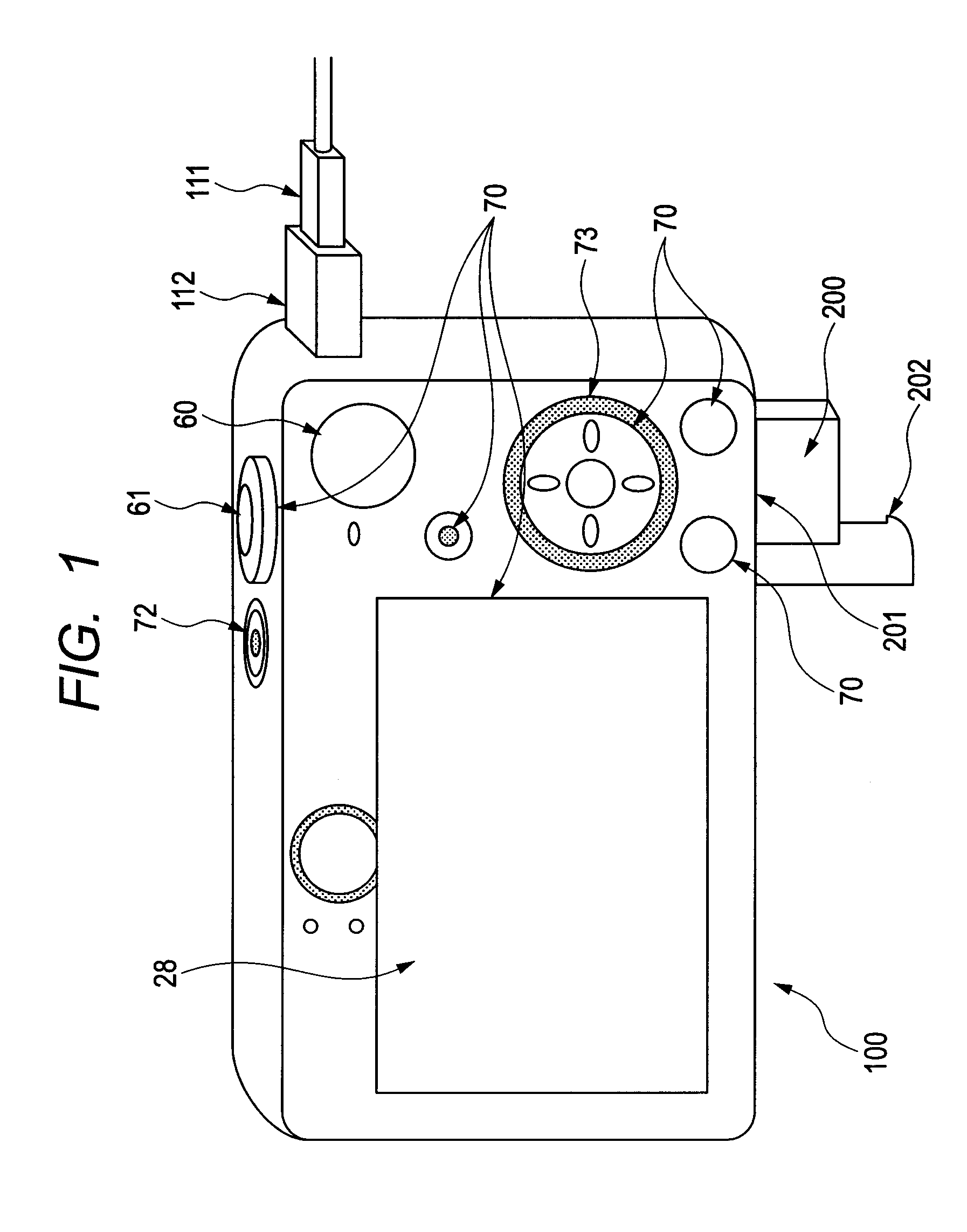
[0047]When a power source is turned on and the operating mode of the digital camera 100 is switched to the photographing mode by the mode change-over switch 60, the photographic mode processing 1 is started.

[0048]In step S301, first, a process for a photographic standby is executed. In the photographic standby process, a through-image display in which the images ...

second embodiment

[0058]In a second embodiment, an example in which the photographic preparation operation is cancelled when “touch-up” is detected at a position out of the area of the shutter icon will be described. The second embodiment differs from the first embodiment with respect to the following point. That is, in the first embodiment, at a point in time when the touch position is moved to a position out of the area of the shutter icon, even if “touch-off” is not performed, the photographic preparation operation is cancelled. On the other hand, in the second embodiment, at the point in time when the touch position has been moved to the position outside of the area of the shutter icon, the photographic preparation operation is not cancelled, but when “touch-up” is subsequently detected at the position outside of the area of the shutter icon, the photographic preparation operation is cancelled.

[0059]FIG. 4 illustrates a flowchart of a photographic mode process 2 as a process in a photographic mod...

third embodiment

[0067]In a third embodiment, an example in which the shutter icon is not displayed but the start of the photographic preparation operation can be instructed by touching an arbitrary position on the through image displayed on the display unit 28 will be described. The photographic preparation operation which is started once may be cancelled when a distance between the “touch-down” position and the “touch-up” position is equal to or larger than a predetermined distance.

[0068]FIG. 5 illustrates a flowchart of a photographic mode process 3 as a process in a photographic mode of the third embodiment. The photographic mode process 3 is realized by a method whereby the system control unit 50 develops the program recorded in the non-volatile memory 56 into the system memory 52 and executes it.

[0069]Since S501 is similar to the processing of S301 mentioned with regard to FIG. 3, its description is omitted here. However, the shutter icon is not displayed in the present embodiment.

[0070]In S50...


PUM


Abstract

An image pickup apparatus controls in such a manner that if a touch applied to a touch operation member is detected by a detection unit arranged to detect a touch operation applied to the touch operation member, a photographic preparation unit makes an adjustment of a photographic setting, and after the touch, if the detection unit detects a predetermined touch operation and thereafter detects that the touch operation member loses the touch applied thereto, a photographic processing unit does not execute a photographic processing, while after the touch, if the detection unit detects that the touch operation member loses the touch applied thereto without detecting the predetermined touch operation, the photographic processing unit executes the photographic processing.

Description

BACKGROUND OF THE INVENTION[0001]1. Field of the Invention[0002]The present invention relates to an image pickup apparatus and, more particularly, to an image pickup apparatus having a touch sensor for detecting touch coordinates.[0003]2. Description of the Related Art[0004]Hitherto, a release switch of a push-button type is generally provided for an image pickup apparatus called a camera, and the release switch has a non-depression state (which is generally a non-manipulated state in which the switch is not depressed), a full depression state in which a push-button causes the release switch to be depressed up to a maximum depression at which point the release switch is fully switched, and a half depression state as an intermediate state between them. In the half depression state (hereinbelow, referred to as SW1) of the release switch, photographing preparation operations such as autofocus control, autoexposure control, and auto white balance control are instructed. Further, when th...

Claims


Application Information

Patent Timeline
IPC IPC(8): H04N5/222
CPCG06F3/0488H04N5/23293H04N5/23216H04N1/0035H04N23/62H04N23/631H04N23/635H04N23/00G06F3/04817G06F3/04847
Inventor SAITO, KYOTA
Owner CANON KK
Learn More