
Communication protocol for low-power network applications and a network of sensors using the same

a technology of low-power network applications and communication protocols, applied in the direction of frequency-division multiplex, wireless architecture, instruments, etc., can solve the problems of inability to physically get, limited placement options of digital cameras, and undesirable long-term monitoring or security applications

Active Publication Date: 2011-09-15
AVAAK
View PDF2 Cites 28 Cited by
  • Summary
  • Abstract
  • Description
  • Claims
  • Application Information

AI Technical Summary

Benefits of technology

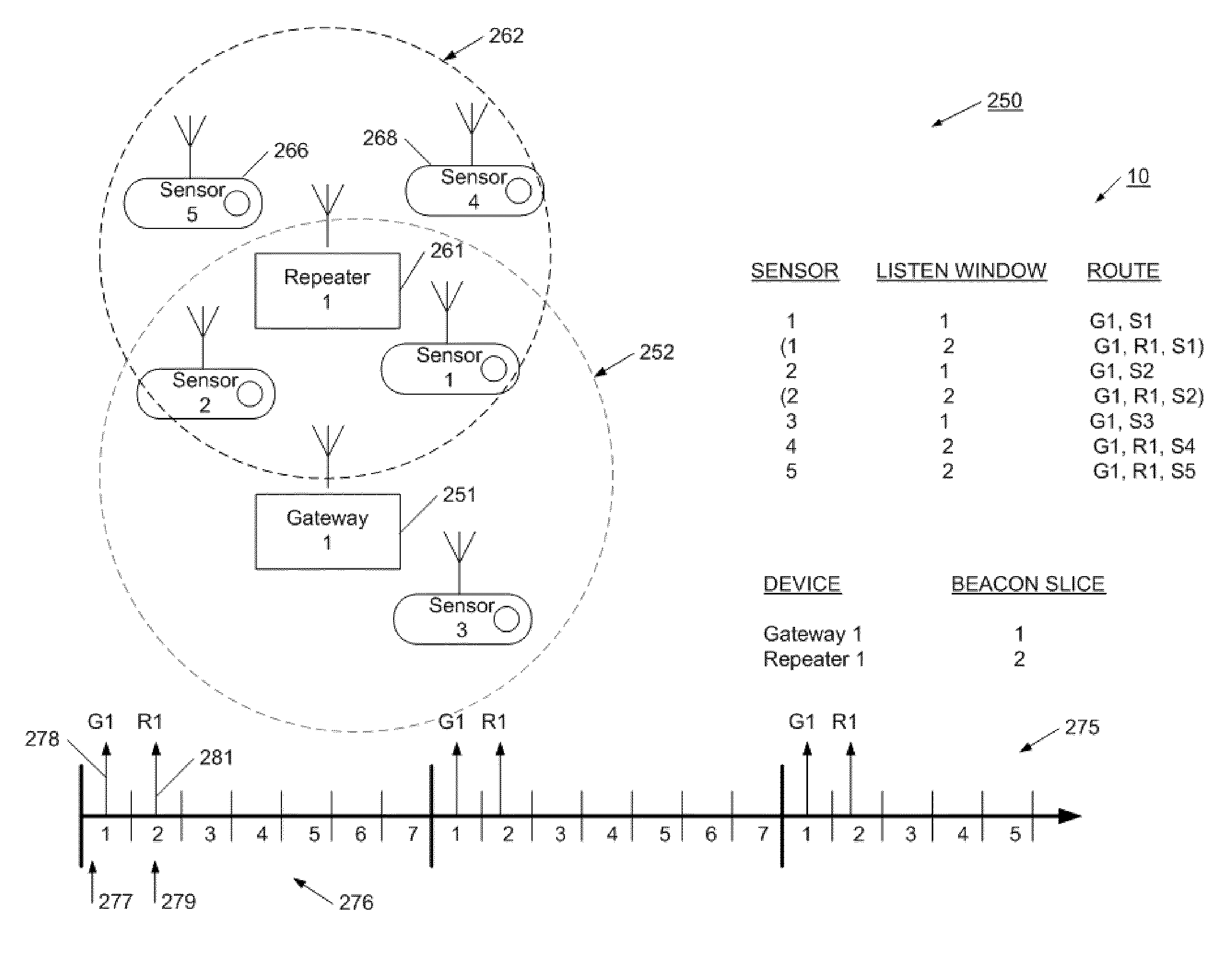
[0008]Briefly, the present invention provides a network sensor system capable of extremely low-power operation. Each sensor is equipped with a radio transceiver for communication purposes. The network sensor system implements a communication protocol that shifts the power burden to a central gateway device that allows the sensors to operate at most times in a sleep mode, where only a low-power time is active. In this way, each sensor's receiver, transmitter, and support circuitry are operated only when strictly necessary. The network has a defined network time frame, and each device maintains and adjusts its own clock and relationship with the network time. In this way, since the network is synchronized, each sensor is aware about when it may be sent a message, and opens a short listen window only when such a message is expected. If no message is received, or if the message is addressed to another sensor, the sensor goes back to sleep. The sensor's transmitter is only activated in the case where the message 1) is received during the listen period, 2) is addressed to the sensor, and 3) requires a transmission action. Otherwise, the transmitter remains deactivated.
[0010]Advantageously, the network sensor system optimally use scarce power resources available at the remote sensors, enabling sensors to operate for long periods of time on only battery power. More particularly, each sensor only needs to operate its receiver from time to time, and needs to use its transmitter only when data is ready to be transmitted and the network device is ready to receive it. Other than these brief times when the radio is active, the sensor is able to operate in a sleep mode, where only an extremely low-power timer is required.

Problems solved by technology

However, the digital camera has batteries that must be regularly replaced, or recharged.
In this way, the digital camera is undesirable for any meaningful long-term monitoring or security applications.
Because the Internet camera needs enduring power, its placement options are limited.
However, these discreet locations are often difficult to physically get to, and do not have ready power sources.
Either option is costly, and disruptive of the target area.
Transmitting these large files may take substantial power, particularly in a wireless installation.
It may be possible to save power by reducing the size of the image file, but important resolution and image detail may also be lost.

Method used


Image

  • Communication protocol for low-power network applications and a network of sensors using the same
  • Communication protocol for low-power network applications and a network of sensors using the same
  • Communication protocol for low-power network applications and a network of sensors using the same

Examples


Embodiment Construction

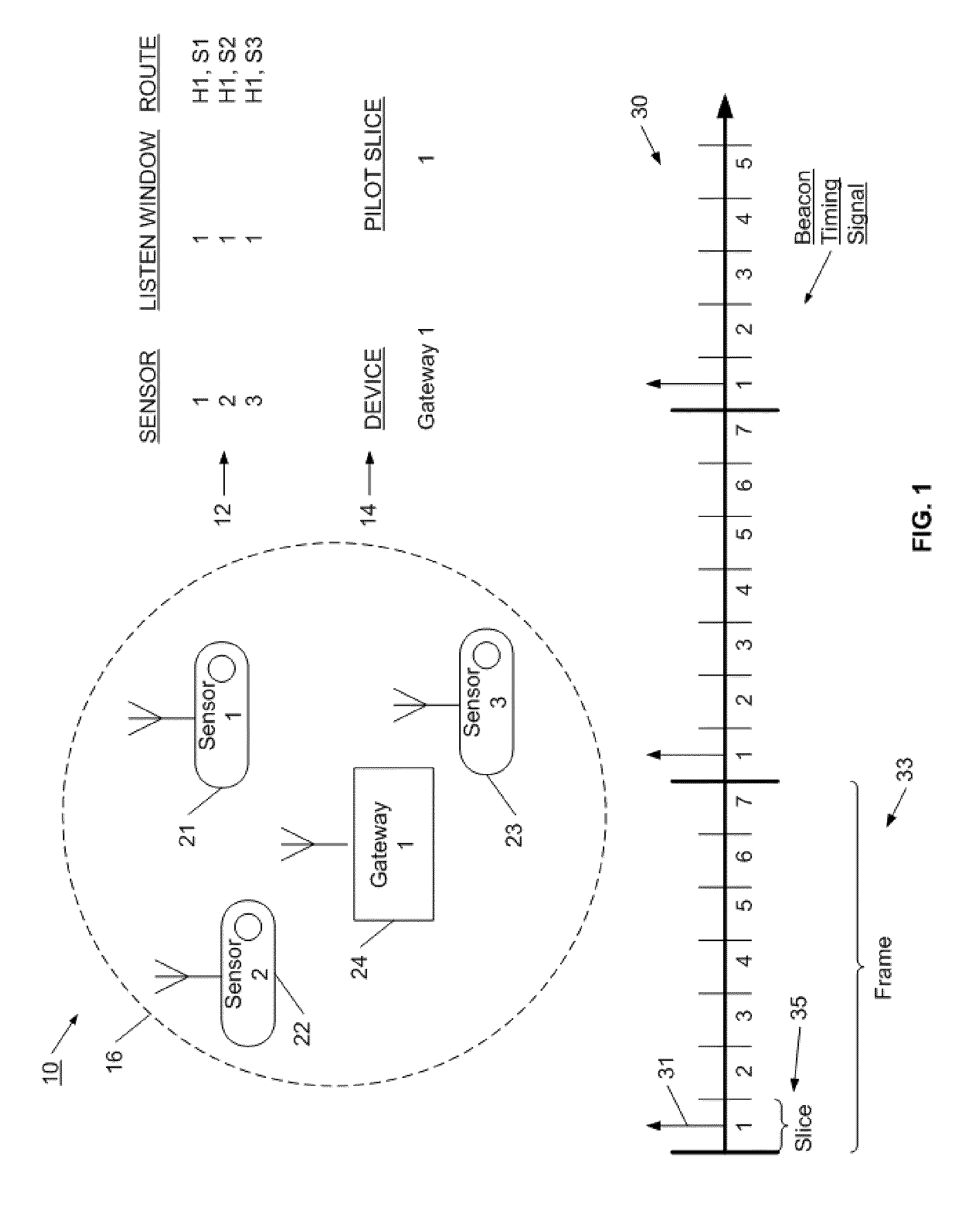
[0030]Referring now to FIG. 1, a network of sensors is illustrated. Network 10 is a wireless network enabling a set of independent sensors to communicate sensor information to a gateway, which may then make the information available for a variety of uses. For example, the gateway may be connected to other central server operations for collecting, sharing, and analyzing the information. In one example, the sensor systems are image cameras for taking image or video information. These sensors may be distributed around a local area for security, surveillance or monitoring purposes.

[0031]In network 10, a gateway 24 acts as the master or controller for the network system. Camera sensors 21, 22, and 23 are positioned within the communication range 16 of gateway 24. Typically, these sensors will be within a few hundred feet or less of gateway 24. It will be appreciated, however, that the distance between sensors, and the distance between each sensor and the gateway may be adjusted according...


PUM


Abstract

A network sensor system is provided that is capable of extremely low-power operation. The network sensor system implements a communication protocol that allows the sensors to operate at most times in a sleep mode, where only a low-power time is active. In this way, each sensor's receiver, transmitter, and support circuitry are operated only when strictly necessary. The network has a defined network time frame, and each device maintains and adjusts its own clock and relationship with the network time. In this way, each sensor is aware about when it may be sent a message, and opens a short listen window only when such a message is expected. If no message is received, or if the message is addressed to another sensor, the sensor goes back to sleep. The sensor's transmitter is only activated in the case where the message 1) is received during the listen period, 2) is addressed to the sensor, and 3) requires a transmission action. Otherwise, the transmitter remains deactivated.

Description

RELATED APPLICATIONS[0001]This application is a continuation-in-part to U.S. patent application Ser. No. 12 / 108,640, filed Apr. 24, 2008, and entitled “Communication Protocol for Low-Power Network Applications and a Network of Sensors Using the Same”; and is related to U.S. patent application Ser. No. 11 / 210,411, issued as U.S. Pat. No. ______, entitled “Network Sensor System and Protocol”, both of which are incorporated herein in their entirety.FIELD OF THE INVENTION[0002]The present invention relates to a protocol for operating a network of devices in a low-power application. More particularly, in one aspect, the present invention relates to a generally synchronous communication protocol that facilitates low-power communication for a set of networked sensors or cameras.BACKGROUND[0003]The field of remote sensing is growing rapidly. Remote sensing has been found to be useful in security applications, as well as for monitoring environmental, commercial and industrial processes. Remo...

Claims


Application Information

Patent Timeline
Patent Type & Authority Applications(United States)
IPC IPC(8): H04W52/02H04W88/04
CPCH04Q9/00H04Q2209/43H04Q2209/30H04Q2209/823H04Q2209/883
Inventor GOLDBERG, BAR-GIORAMESSINGER, GIOIAAOE, ANDY CHENG-HSIN
Owner AVAAK
Learn More