Systems and methods for 2D image and spatial data capture for 3D stereo imaging

a technology of spatial data and image capture, applied in the field of three-dimensional (3d) stereo imaging, can solve the problems of insufficient collection of geometrically inaccurate to the original scene, and the actual image-capture process is not accurate enough to collect true 3d information for the given scene. , to achieve the effect of accurate range data determination and simplified addition of cg visual effect elements

Inactive Publication Date: 2011-09-15
SHAPEQUEST
View PDF6 Cites 239 Cited by
  • Summary
  • Abstract
  • Description
  • Claims
  • Application Information

AI Technical Summary

Benefits of technology

[0011]An aspect of the disclosure includes creating a depth map or “disparity map” using gray-scale variations to represent distances from the camera (or reference coordinates) associated with one or more objects in the scene. The process of creating the disparity map can be made semi-automatic using image data from multiple calibrated cameras. The range data in the disparity map is transformed to match the perspective and viewing frustum of the cinemagraphic (“cine”) camera. The 2D photographed image from the cine camera is embedded with the range data at sub-pixel accuracy to facilitate post-production to create an accurate and more continuous 3D stereo pair from this true 3D data.
[0014]Multiple cameras with relatively large separations (i.e., typically much greater that the interocular separation of about 65 mm) are configured to capture 2D images over their respective field of views and over an overlapping volume associated with a scene having one or more objects. One or more of the cameras serve as reference or “witness” cameras that allow for accurate range data determination using photogrammetry techniques to calculate the object distances. The witness cameras are synchronized with respect to the shutter of the main cine camera.
[0015]The addition of CG visual effect elements is simplified by the present disclosure because the systems and methods result in the creation of a virtual 3D geometry of the location and allows for dual virtual cameras to be placed substantially arbitrarily in the virtual 3D space.

Problems solved by technology

The process of “converting” 2D photographed images into three-dimensional 3D stereo images (left eye and right eye pairs) for the motion picture and television industry is extremely labor intensive, time consuming, financially expensive, and has the added problem of being geometrically inaccurate to the original scene.
However, the available 3D technologies do so through interpretive and creative means, or through system configurations that do not capture the true depth and geometry of the original environment using the 2D photography.
While this allows for creation of a 3D effect, the actual image-capture process does not collect a substantial amount of true 3D information for the given scene mainly because the interocular distance DH is too small relative to the distance DS.
This lack of accurate volumetric data and true 3D geometry provides significant problems and challenges when visual effects such as computer-generated elements need to be added to the photographed or filmed scenes.
However, in 3D movie post-processing, the jet contrail is also in 3D and thus is much more difficult to remove.
Because of the limitations of present-day 3D imaging technology, critical 3D-stereo-related decisions must made at the time of shooting rather than in post-production.
The addition of visual effects in the form of computer-graphics (CG) environments and CG characters into scenes that have been originally shot in 2D and converted into 3D stereo further complicates matters and poses great technical and financial challenges to visual effects post-production.

Method used


Image

  • Systems and methods for 2D image and  spatial data capture for 3D stereo imaging
  • Systems and methods for 2D image and  spatial data capture for 3D stereo imaging
  • Systems and methods for 2D image and  spatial data capture for 3D stereo imaging

Examples


Embodiment Construction

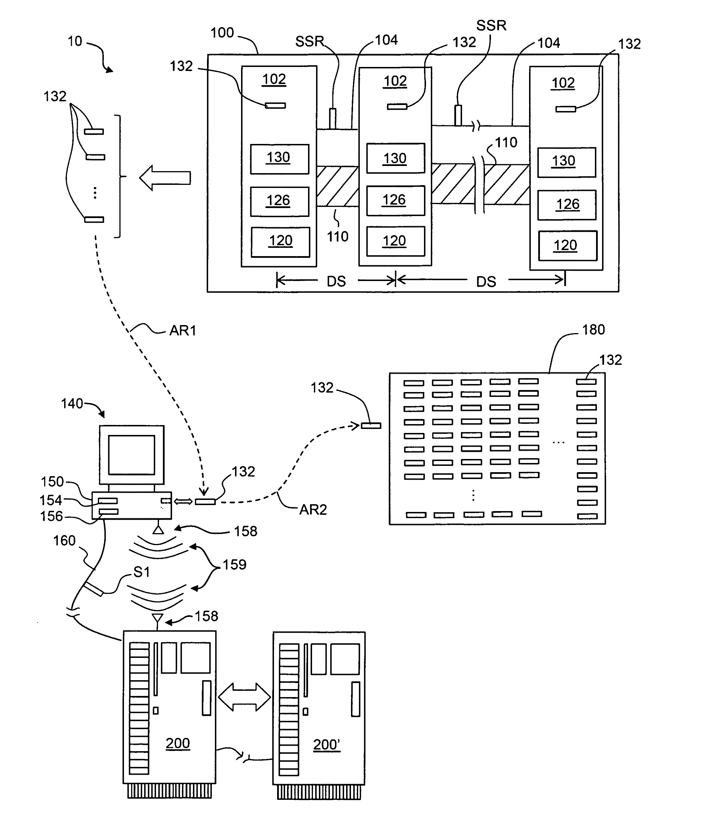
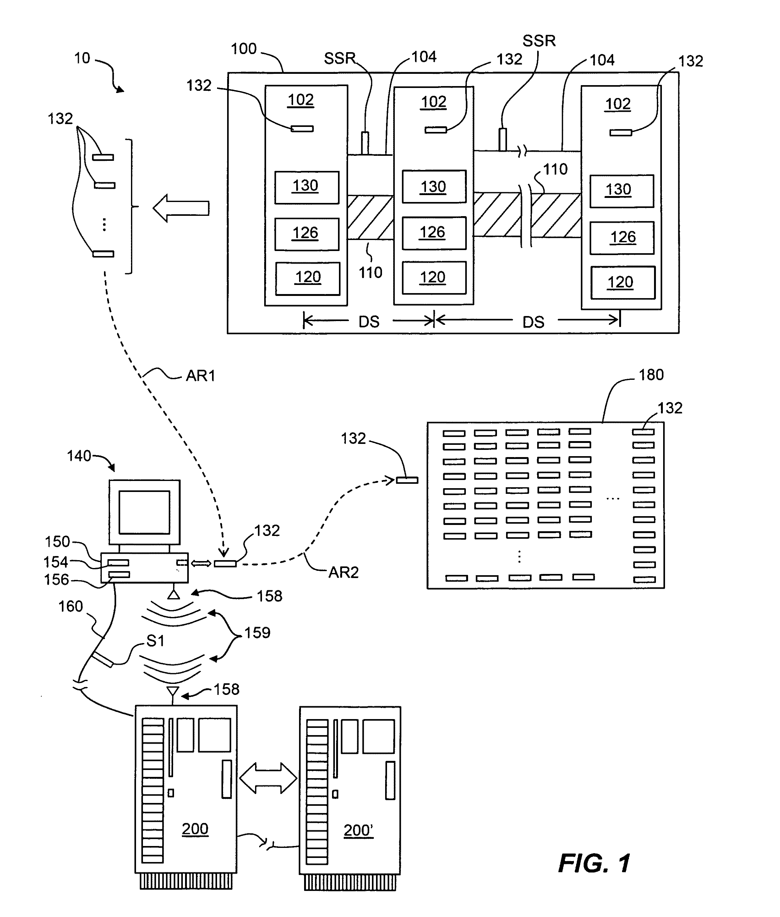
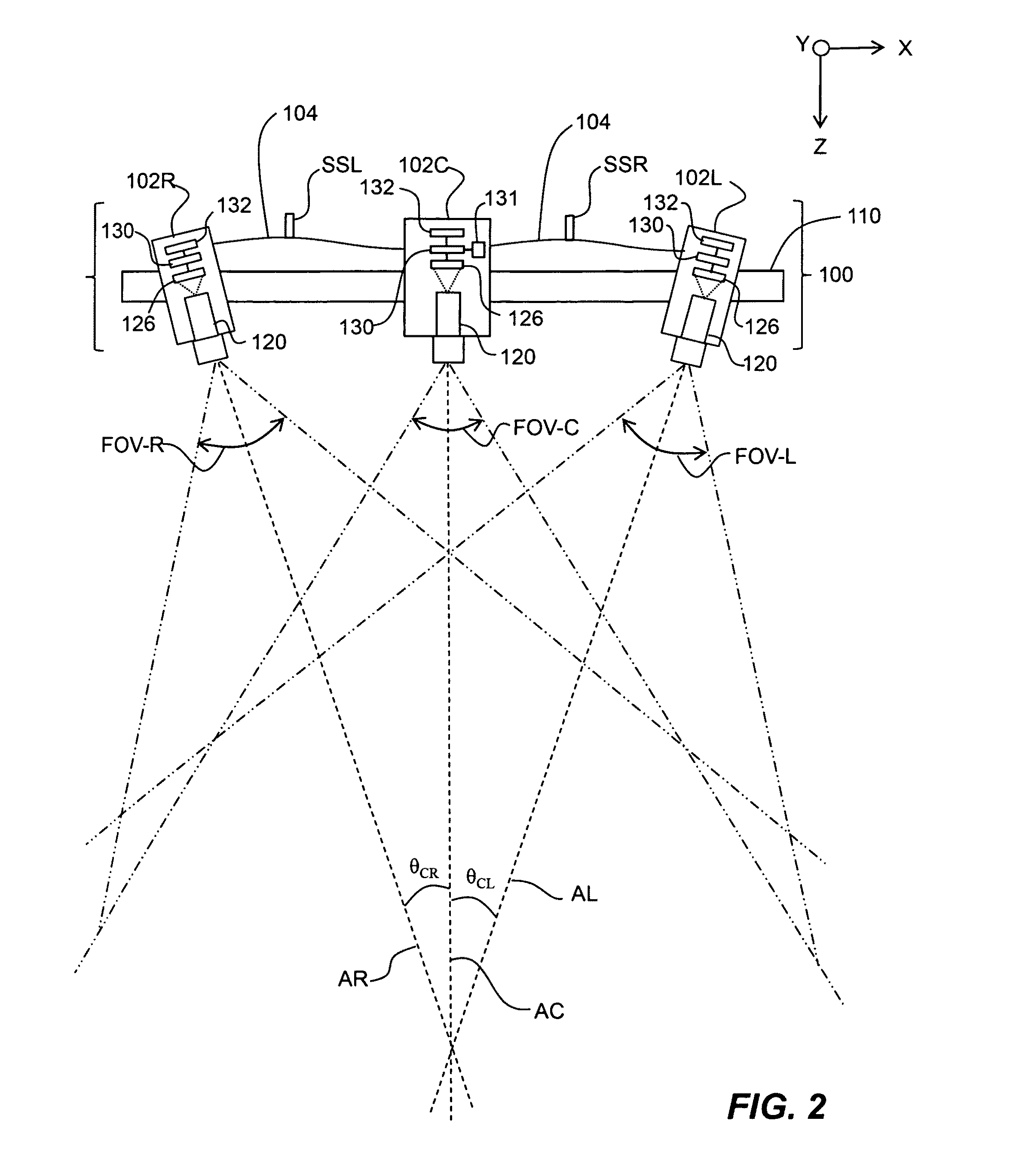
[0043]The present disclosure relates generally to creating three-dimensional (3D) stereo images from two-dimensional (2D) photography, and in particular to systems and methods for 2D image capture and post-processing for 3D stereo imaging. The disclosure sets forth an overview of the 3D stereo imaging system and its components. The various components of the 3D stereo imaging system are then described in greater detail. Then, a variety of embodiments of the methods of the disclosure based on the operation of the 3D stereo imaging system are described. The terms “right” and “left” as applied to the witness cameras are relative to the 3D imaging system and its view of the scene.

[0044]Various algorithms used to carry out the systems and methods of the invention are described herein along the way, and are also set forth in more detail in an “algorithms” section toward the end of this Detailed Description.

3D Stereo Imaging System

[0045]FIG. 1 is a generalized schematic diagram of the 3D st...


PUM


Abstract

Systems and methods for 2D image and spatial data capture for 3D stereo imaging are disclosed. The system utilizes a cinematography camera and at least one reference or “witness” camera spaced apart from the cinematography camera at a distance much greater that the interocular separation to capture 2D images over an overlapping volume associated with a scene having one or more objects. The captured image date is post-processed to create a depth map, and a point cloud is created form the depth map. The robustness of the depth map and the point cloud allows for dual virtual cameras to be placed substantially arbitrarily in the resulting virtual 3D space, which greatly simplifies the addition of computer-generated graphics, animation and other special effects in cinemagraphic post-processing.

Description

CLAIM OF PRIORITY[0001]This application claims the benefit of priority under 35 U.S.C. §119(e) of U.S. Provisional Application Ser. No. 61 / 312,330, filed on Mar. 10, 2010, which application is incorporated by reference herein.FIELD[0002]The present disclosure relates generally to creating three-dimensional (3D) stereo images from two-dimensional (2D) photography, and in particular to systems and methods for 2D image capture and spatial data capture for 3D stereo imaging.BACKGROUND ART[0003]The process of “converting” 2D photographed images into three-dimensional 3D stereo images (left eye and right eye pairs) for the motion picture and television industry is extremely labor intensive, time consuming, financially expensive, and has the added problem of being geometrically inaccurate to the original scene.[0004]Current technologies allow for the creation of 3D stereo imaging from 2D photography. However, the available 3D technologies do so through interpretive and creative means, or t...

Claims


Application Information

Patent Timeline
Patent Type & Authority Applications(United States)
IPC IPC(8): G06K9/00H04N13/239H04N13/243
CPCH04N13/00G06T2207/10012H04N13/0239H04N13/0425H04N13/0257G06T7/0075H04N13/0246H04N13/0271H04N13/0242H04N13/0275H04N13/026G06T7/593H04N13/239H04N13/243H04N13/246H04N13/257H04N13/261H04N13/271H04N13/275H04N13/327
Inventor YEATMAN, JR., HOYT H.ROBERTSON, GARY
Owner SHAPEQUEST
Why Eureka
Try Eureka