
Electronic apparatus, transmitter, amplifier, and amplifier control method

a technology of amplifier control and electronic equipment, applied in the direction of amplifiers with semiconductor devices/discharge tubes, antennas, electric long antennas, etc., can solve the problems of high-speed devices that cannot be mounted, increase power consumption, and insufficient supply of power,

Inactive Publication Date: 2011-09-15
FUJITSU LTD
View PDF5 Cites 29 Cited by
  • Summary
  • Abstract
  • Description
  • Claims
  • Application Information

AI Technical Summary

Problems solved by technology

Mounting such a high-speed device is costly and increases power consumption.
This results in an excess or insufficient supply of power at a peak time.
However, even when the agreement of one peak value is achieved using an offset, the agreement of other peak values cannot be achieved and thus, an excess or insufficient supply of power occurs.
Thus, an efficient supply of power cannot be achieved simply by making a drain voltage proportional to an envelope.

Method used


Image

  • Electronic apparatus, transmitter, amplifier, and amplifier control method
  • Electronic apparatus, transmitter, amplifier, and amplifier control method
  • Electronic apparatus, transmitter, amplifier, and amplifier control method

Examples


Embodiment Construction

[0031]In the known method in which an envelope is converted by referring to the LUT 904, since an original envelope is converted by primary conversion, an envelope tracking signal is sensitive to the effect of the original envelope. Therefore, the known method described above has the following problems.

[0032]First, since a voltage higher than or equal to a lower limit of an operating range of a source voltage is supplied to a signal below the lower limit, unnecessary power consumption occurs. For example, as indicated by an arrow 918 in FIG. 10, a difference between the envelope tracking signal 916 and the envelope tracking signal 917 represents such unnecessary power consumption.

[0033]Also, when an output corresponding to a peak of a waveform determined by referring to a look-up table exceeds an original peak value, excess power is supplied at a peak time. For example, as indicated by an arrow 919 in FIG. 10, a difference between the envelope tracking signal 916 and the envelope tr...


PUM


Abstract

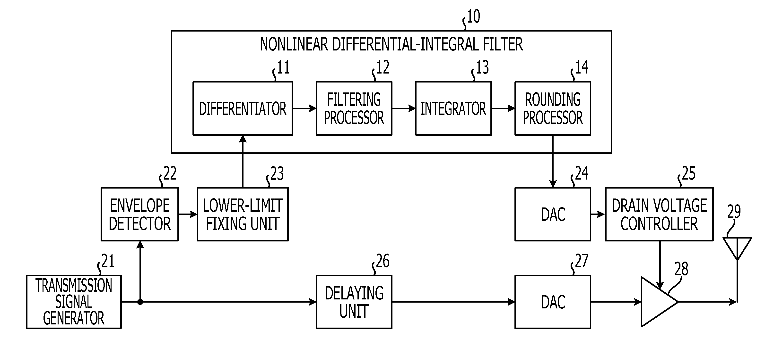
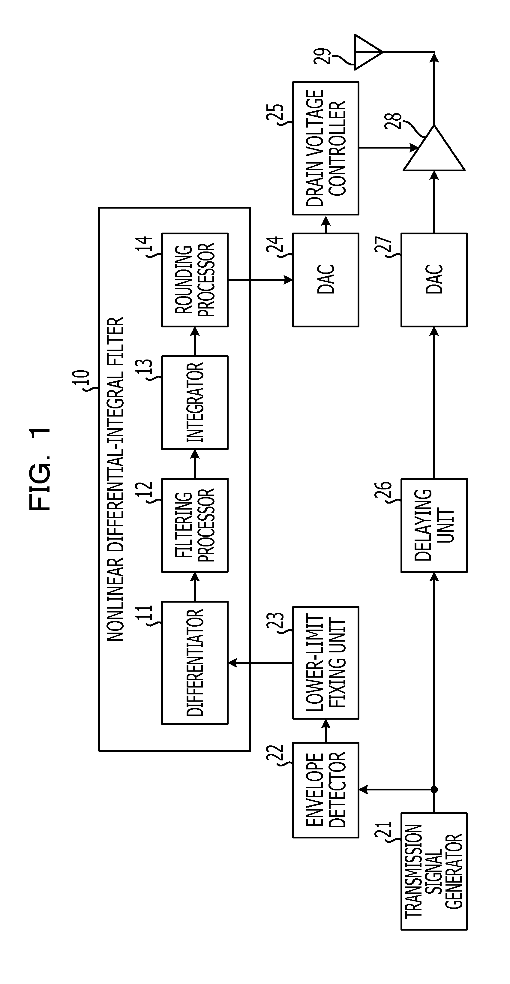
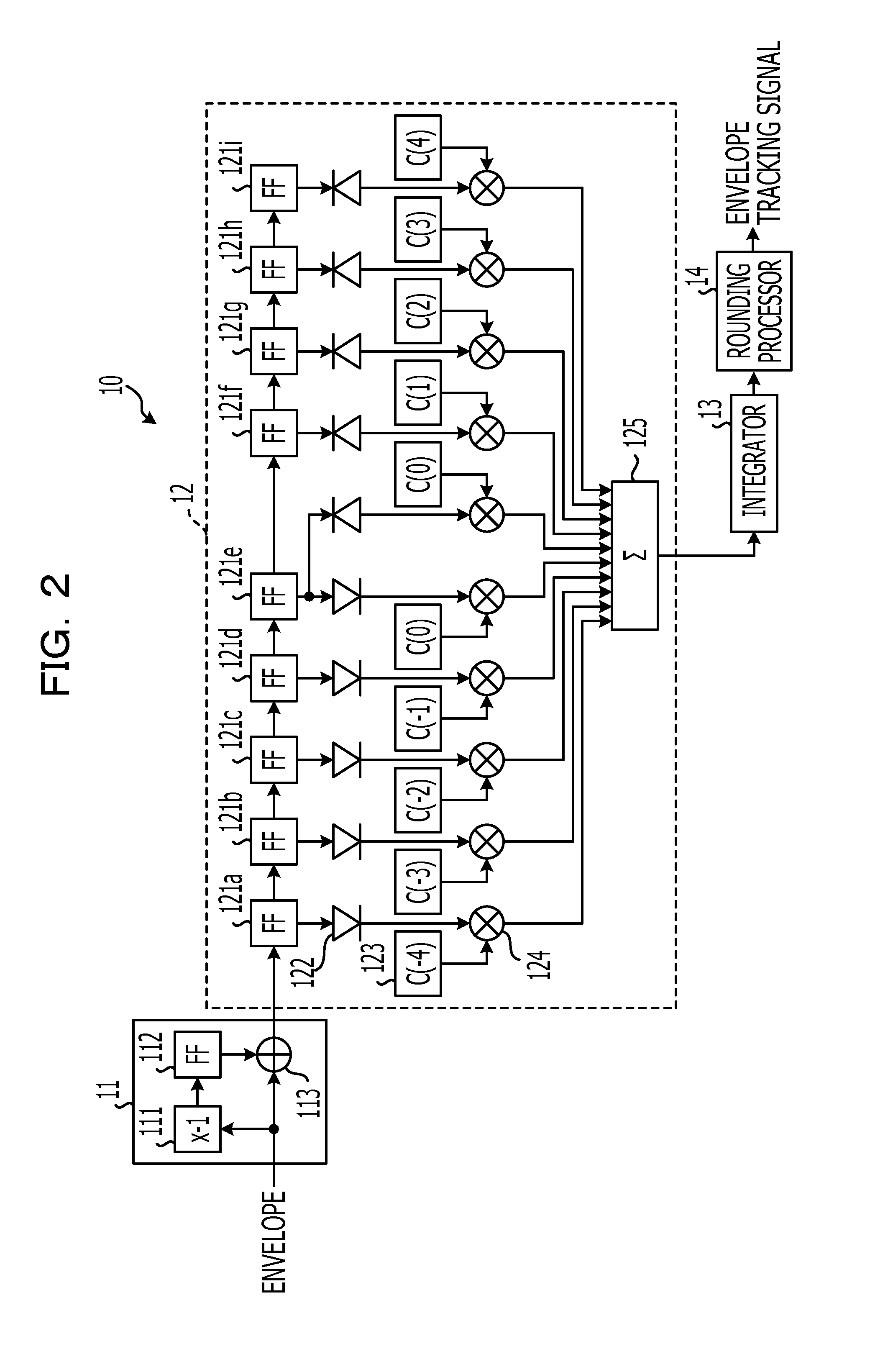
An electronic apparatus having communications capabilities, including: an envelope detector that detects an envelope of a transmission signal; a differentiator that differentiates the envelope with respect to time to obtain differential components; a filtering processor that filters the differential components; an integrator that integrates the filtered differential components with respect to time to generate an envelope tracking signal; an amplifying unit that amplifies the transmission signal; and a voltage controller that controls, in accordance with the envelope tracking signal, a voltage the amplifying unit uses to amplify the transmission signal.

Description

CROSS-REFERENCE TO RELATED APPLICATIONS[0001]This application is related to and claims priority to Japanese Patent Application No. 2010-56584 filed on Mar. 12, 2010 and herein incorporated by reference.BACKGROUND[0002]1. FIELD[0003]The present invention relates to an electronic apparatus, a transmitter, an amplifier, and an amplifier control method.[0004]2. Description of the Related Art[0005]Envelope tracking (ET) is known as a technique that improves efficiency of power use in an amplifier included in a transmitting unit of an electronic apparatus, such as a mobile terminal or a radio relay apparatus. Examples of the envelope tracking include a technique that improves efficiency of power use in an amplifier by controlling a drain voltage in accordance with changes in the envelope of a transmission signal (drain voltage control (DVC)).[0006]Specifically, drain voltage control is a technique that changes a drain voltage of an amplifier in accordance with the amplitude of an envelope...

Claims


Application Information

Patent Timeline
IPC IPC(8): H04B1/02H03F1/00
CPCH03F1/0222H03F3/245H03F2200/102
Inventor HAMANO, MITSUHARU
Owner FUJITSU LTD
Learn More